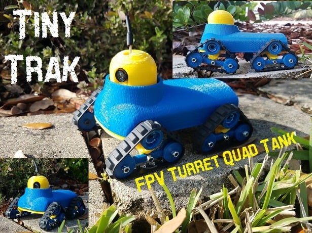
Tiny Turret Quad Track - Tiny Servo Driven FPV RC Tank - Tiny Trak
thingiverse
This tiny FPV Turret Quad Tank uses Lego tracks driven by servos. It turns via skid steer. The tracks can articulate 30 degrees up and down for going over obstacles. The camera turret is controlled by a servo connected to the yaw on the receiver and allows for looking side to side while driving. (#TinyTrak) When designing the second iteration of this tank, my kids thought it looked like a Minion driving a tank. To build you need the following: -Four Lego tracks (Lego Part: x939 or 43903 - www.bricklink.com for best prices) -Four servos (continuous [FS90R] or modify a regular one – Search "FliteTest 360 Degree Servo Mod" on YouTube) -One (Regular) servo for the turret -Receiver of your choice (the smaller the better) -Mini FPV camera AIO (I used this one: AKK BA2 5.8Ghz 200mW FPV Transmitter Raceband 600TVL 1/4 Cmos Mini FPV Micro AIO Camera (https://www.akktek.com/akk-ba2.html) -5v pololu step up/down regulator -1s or 2s batteries (I used tattu 800mah); I ran two 1s batteries inside. -Twelve M3-0.5 x 14mm socket cap screws/bolts (or similar) – you could use M3x12mm, but the 14mm are better. -Twelve M3-0.5 Nylon lock nuts Quick Test video: https://youtu.be/Fby9BBVEY9s https://youtu.be/qsbE4UCF-jk This is my third Tiny Track design and second iteration of the Quad Track. (See the originals at https://www.thingiverse.com/thing:2977620) and https://www.thingiverse.com/thing:3464889). A Note on Printing: All parts can be printed WITHOUT SUPPORTS. These files were designed with integrated supports. There may be some tabs to cut out (See Assembly Instructions). Print: -One Turret Body (has integrated supports) -One Turret Chassis -One Turret (or one Turret Upsidedown – depending on how you wish to print with integrated supports) -One Disk (has integrated supports) -Four Lower Suspensions (has integrated supports) -Four Transverse Levers -Four driven wheels (four of both Driven Wheel A & B) -Sixteen Bogey Wheels (Non-drive) Radio Set-up: When setting your radio up for controlling this tank, you will use Delta Wing mixing. This will mix the elevator and aileron signals to allow the tank to turn and move using only the right stick (for Mode 2 Radios). If using the turret camera function, that servo will be plugged into the Yaw signal port. Assembly: 1. Print all required parts. (Figure 1) 2. Cut/remove the print tabs from the “Turret Body” and “Lower Suspension” prints. (Figures 2, 3, & 4) 3. Ensure the “Turret Body” and “Turret Chassis” click together and have a good fit. parts should go together and come apart without much effort. (Figure 5) 4. Install continuous servos and regular servo into the “Turret Chassis.” Consider cutting down the wires and soldering the leads together to save on space. Make sure to connect the left side signal wires together and then the right side signal wires together (either direct soldering or using a Y-harness). Then connect all of the positive and negative leads together respectively for all four servos. Connect the power leads to to a 5V regulator/Pololu. Attach power and signal wires to the receiver of your choice. (Figure 6) 5. Super Glue (CA Glue) the “Driven Wheel A & B” Parts together. Once dry, glue in the included servo arm in the driven wheel slot. ensure the hole in the servo arm is centered. (Figure 7). Give this ample time to completely dry and set up. Then cut the servo arm tab hanging off the wheel. 6. Install the driven wheels onto the servos (Figure 8) 7. Install the “Transverse Lever” onto the “Lower Suspension.” Ensure the flat or smooth part of the lever - typically the part that printed down on the print bed - is facing the “lower suspension.” This will help reduce friction. Install the four “bogey Wheels” onto the lever. again, ensure the smooth face of the bogey wheels face the lever to reduce any friction. (Refer back to Figure 7) 8. With the Chassis flipped over, glue the lower suspension assembly (four) to the chassis. BE SURE TO LINE UP THE TRANSVERSE LEVER AND THE DRIVEN WHEEL in the same plane. also make sure the center bolt of the lever is in line with the center of the driven wheel. (Figure 9 & 10) 9. Install the Body onto the Chassis. Remove the integrated support from the “Disk”. Glue a servo horn onto the bottom of the “Disk” and allow to dry. (Figure 11) 10. Attach the “Disk” to the servo in the turret gap. Don't install the servo screw to connect the disk to the servo. This will allow the easy removal of the turret for changing out batteries. (Figure 12) 11. Ensure the FPV Camera fits into the “Disk”. (Figure 13). 12. Install the Turret cover onto the disk. (Figure 14). 13. Install LEGO Tracks (Figure 15) 14. Figure 16 shows how I have my batteries placed in the compartment (Figure 16). 15. Bind your radio and get moving. Experiment with different track configurations 16. Enjoy
With this file you will be able to print Tiny Turret Quad Track - Tiny Servo Driven FPV RC Tank - Tiny Trak with your 3D printer. Click on the button and save the file on your computer to work, edit or customize your design. You can also find more 3D designs for printers on Tiny Turret Quad Track - Tiny Servo Driven FPV RC Tank - Tiny Trak.