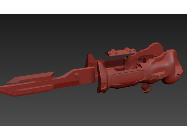
Titanfall Data Knife - Advanced Version for Electronics
thingiverse
Quite a long and complex code snippet! I'll try to provide some feedback on how to improve the `advancePixel()` function, which seems to be the main focus of this code. **Consolidate repeated logic** The three `if` statements inside `advancePixel()` are similar and can be consolidated into a single loop. This will reduce code duplication and make it easier to maintain. ```c void advancePixel() { int pixels[] = {currentPixel, nextPixel, oppositePixel}; for (int i = 0; i < 3; i++) { if (pixels[i] == 6) { pixels[i] = 1; } else { pixels[i]++; } } // ... rest of the function remains the same ... } ``` **Extract a separate function for incrementing pixels** The logic inside `advancePixel()` can be extracted into a separate function, making it easier to reuse and test. ```c void incrementPixels(int* pixels, int numPixels) { for (int i = 0; i < numPixels; i++) { if (pixels[i] == 6) { pixels[i] = 1; } else { pixels[i]++; } } } void advancePixel() { incrementPixels(¤tPixel, 1); incrementPixels(&nextPixel, 1); incrementPixels(&oppositePixel, 1); // ... rest of the function remains the same ... } ``` **Consider using a struct or class for pixel state** The `advancePixel()` function seems to be tightly coupled with the individual pixel variables (`currentPixel`, `nextPixel`, `oppositePixel`). Consider grouping these variables into a struct or class, which can encapsulate their behavior and make it easier to manage. ```c struct PixelState { int current; int next; int opposite; }; void advancePixel(PixelState& state) { incrementPixels(&state.current, 1); incrementPixels(&state.next, 1); incrementPixels(&state.opposite, 1); } ``` These are just some suggestions to improve the code. Let me know if you'd like more feedback or have any specific questions!
With this file you will be able to print Titanfall Data Knife - Advanced Version for Electronics with your 3D printer. Click on the button and save the file on your computer to work, edit or customize your design. You can also find more 3D designs for printers on Titanfall Data Knife - Advanced Version for Electronics.