TrackIR ProClip magnetic battery mount
thingiverse
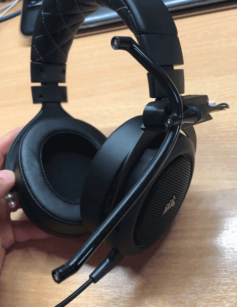
Having purchased a Corsair HS70 wireless headset I wanted a wireless version of the TrackIR ProClip to go with it. Using this mount I now have an active clip with a battery life measured at around 35 hours that mounts magnetically and switches on and off automatically. If you don't wish to use the button then it can be wired up in an even easier manner and the LEDs can be turned off by simply unplugging the battery when not in use. Parts (in addition to filament) * [6off 8x2 magnets - I used 8x2 N42 1kg pull magnets that I already had](https://www.first4magnets.com/circular-disc-rod-c34/8mm-dia-x-2mm-thick-n42-neodymium-magnet-1kg-pull-p3010#ps_0_3056|ps_1_16656) * [Crazepoly-UK 230mAh 1S 3.8v LiPo battery - this item includes a connector with wires](https://smile.amazon.co.uk/gp/product/B07L4JWDWW/ref=ppx_yo_dt_b_asin_title_o03_s01?ie=UTF8&psc=1) * [1S LiPo USB charger (if you don't have one already)](https://smile.amazon.co.uk/gp/product/B074MQ8WF2/ref=ppx_yo_dt_b_asin_title_o03_s00?ie=UTF8&psc=1) * [6x6x4.3 tactile button - I used one from this set](https://smile.amazon.co.uk/gp/product/B01N67ICEC/ref=ppx_yo_dt_b_search_asin_title?ie=UTF8&psc=1) * Small M3 screw * Thin wire - I used 26AWG silicone insulated wire, but anything thin enough to fit should be fine * Heatshrink tube The bottom mount was made to fit the Corsair HS70 headset. You'll probably need to mod the base to suit different headsets. # Print Settings I used support enforcers around the battery opening to allow for the curve, plus a little inside the larger LED arm mount hole to ensure roundness. You should add pauses in the print for the base body and battery holder to insert the magnets. There are three magnets in each body and I aranged them with the outer magnets north-up, and the inner magnet south-up. This way the clip will self-locate in the correct position. ** You MUST ensure that the magnets in each body correspond correctly or it won't clip together ** There are many examples of gcode snippets you can use to pause and add inserts - I used this with the Insert GCode option in Slic3r: ; Pause to insert magnets G1 X10.000 Y200.000 E0 ; parking position ; Move print head up proportionally of print height to max {if layer_z < max_print_height}G1 Z{z_offset+min((layer_z/max_print_height)*(max_print_height-100)+100, max_print_height)}{endif} M400 ; Finish moves M300 S2500 P1000 ; beep M0 Add Inserts ; User stop with message M105 ; return to current temp Ensure this happens just before the layer change on the layer before the holes are covered. Again ensure the magnets are correctly orientated! # How to build Ease out the backing strip and end plugs on the swingarm to free the LED arm. Ensure that you remove the padding from inside the clip so you can take the small resistor as well. Keep the remaining bits in case tyou change your mind so you can reassemble your TrackClip Pro with no more damage than a couple of soldered wires. Remove the support and clean up any residue with a sharp knife or scalpel. Once cleaned up the button and battery should fit easily but sit firmly in place, but be removable with ease. ## **Test fit the LED arm** The LED arm should push easily into the larger mount after you've fed the wires though, not forgetting the o-ring that will give it the correct fit and friction. It will be a little loose at first, but just use a short M3 screw to spread the two arms and secure it properly. The wiring should easily escape beween the arms and around the screw head. ## **No button option** (skip this if you're fitting the button) If you don't want to use the button, you can simply wire the positive (red) wire from the battery connector to the resistor on the LED arm, and the negative (black) wire from the battery connector to the black wire of the LED arm. You can cut and resolder the resistor and black wire from the LED arm so that it fits inside the channel behind the arm mount to keep things tidy. Use some heatshrink to insulate the connections and make it look good, and keep the wires short enough . You're basically done with the battery holder. ## **Button option** If you fit the button your magnetic clip will switch on only when it's clipped to the base (or any other metal item). This is managed by fitting a small button in the base such that it _just_ sticks out enough to be activated when the parts clip together. 1. Take a 6x6x4.3mm tactile button 2. Clip off the two legs on one side, as close as possible 3. Cut the two legs on the other side short. Leave them long enough to solder wire to though. 4. Press the button into the hole underneath the LED arm holder and sit it on a flat surface 5. Press down the assembly and ensure that when the button is pressed the holder sits flush against the surface. If it doesn't, remove the button and sand it with 400-600 grit sandpaper to reduce its height slightly. I had to take off about 0.1mm to make it perfect 6. Feed a red wire (battery positive) and yellow wire (switched positive) through the channel and out of the button hole. Solder the wires to the button - it doesn't matter which way round - and press-fit the button feeding the wires back through for a clean finish. 7. Wiring for button: * Solder the battery connector positive (red) wire to the button red wire * Solder the battery connector negative (black) wire to the LED black wire * Solder the button switched positive (yellow) wire to the LED resistor on the positive wire ** Trim the wires beforehand so that it's tidy, but long enough so that you can easily connect and disconnect the battery when needed. Don't forget to use heatshrink tube to insulate the connectors and tidy the loose wires.** If you're careful when trimming the wires you can get a really clean finish where the resistor is hidden inside the wiring channel. ## **Assemble the headset base** The base that attaches to the headset is in two parts and fits around the earphone mount. It's designed so it can slip over and glue to itself and not to the headset so it can be removed without damaging the headset. Just put a thin layer of superglue on the chamfered parts and, ideally, some superglue activator on the other part, slip them over the earphone mount ENSURING THAT THE MAGNETS FACE OUT, slide them together and hold in place for a few seconds until the glue has cured.
With this file you will be able to print TrackIR ProClip magnetic battery mount with your 3D printer. Click on the button and save the file on your computer to work, edit or customize your design. You can also find more 3D designs for printers on TrackIR ProClip magnetic battery mount.