Trigorilla pro schematics and reverse engineering
thingiverse
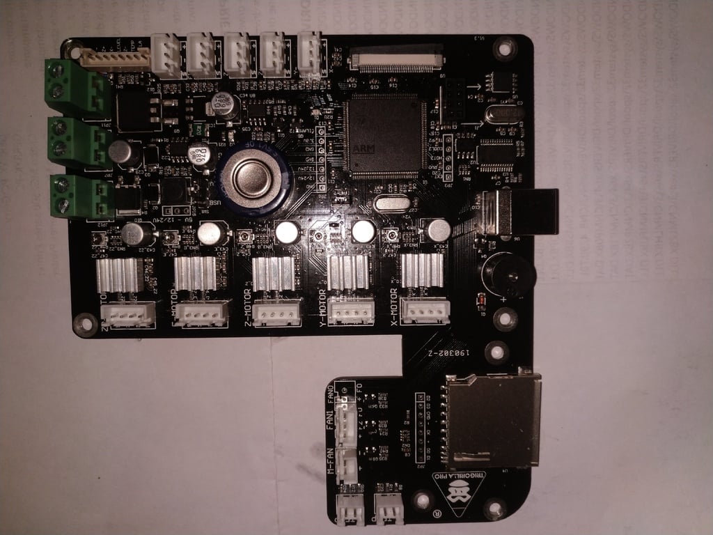
It appears you are referring to a wiring diagram for an LCD display with a resistive touch controller TSC2046 on SPI1 and various other peripherals. I'll outline the key points. ## Key Connections: ### LCD Display (ILI9488): * CSX: PD7 * D/CX: PD11 * WRX: PD5 * RD: PD4 * RESET: PF11 ### Resistive Touch Controller TSC2046 on SPI1: * nIRQ: PB6 * DO: PA6 * DI: PA7 * nCS: PB7 * CLK: PA5 ### Other Peripherals and Power Connections: * GND: Various (connected to ground) * 3V3: Various (powered by a 3.3V supply) * NC: No Connect (connections not used) ## LCD Display Pins Mapping: Here's how the LCD display pins are mapped to the microcontroller pins based on the provided data: | LCD Pin | Microcontroller Pin | | --- | --- | | 1 | GND | | 2 | 3V3 | | 3 | 3V3 | | 4 | PD7 (CSX) | | 5 | PD11 (D/CX) | | 6 | PD5 (WRX) | | 7 | PD4 (RD) | | 8 | PF11 (RESET) | | 9 | PD14 (DB0) | | 10 | PD15 (DB1) | | 11 | PD0 (DB2) | | 12 | PD1 (DB3) | | 13 | PE7 (DB4) | | 14 | PE8 (DB5) | | 15 | PE9 (DB6) | | 16 | PE10 (DB7) | | 17 | PE11 (DB8) | | 18 | PE12 (DB9) | | 19 | PE13 (DB10) | | 20 | PE14 (DB11) | | 21 | PE15 (DB12) | | 22 | PD8 (DB13) | | 23 | PD9 (DB14) | | 24 | PD10 (DB15) | This mapping shows how the LCD display pins are connected to the microcontroller pins. ## Resistive Touch Controller TSC2046 Mapping: Here's how the resistive touch controller pins are mapped to the microcontroller pins based on the provided data: | TSC2046 Pin | Microcontroller Pin | | --- | --- | | nIRQ | PB6 | | DO | PA6 | | DI | PA7 | | nCS | PB7 | | CLK | PA5 | This mapping shows how the resistive touch controller pins are connected to the microcontroller pins. ## Power and GND Connections: * GND: Various (connected to ground) * 3V3: Various (powered by a 3.3V supply) These connections provide power to various components on the board. Note that this is based on the provided data, and you should consult the datasheet for the specific LCD display and resistive touch controller used in your project for accurate information.
With this file you will be able to print Trigorilla pro schematics and reverse engineering with your 3D printer. Click on the button and save the file on your computer to work, edit or customize your design. You can also find more 3D designs for printers on Trigorilla pro schematics and reverse engineering.