Tronxy X5SA linear guides
thingiverse
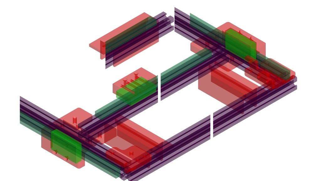
The conversion can be carried out in several separate steps, since the levels of the rollers cannot be changed, the Y-axis can be upgraded on one side and only the second side later, or only the X-axis first. You need for the X-axis: 1 piece MGN12 rail; 500mm with MGN112H carriage 10 pieces flat head screw M3x8 10 pieces of T-nut sliding M3 Assembly tools and guide block (3d printing) 4 pieces flat head screw M3x16 8 pieces flat head screw M3x10 (4 pan head screws M5x20) Convert the X-axis, print out the assembly tools and guide block, dismantle the extruder and the cable bridge, remove the belt and dismantle the carriage, center the front and rear carriage bridge with two screws, note the correct position and drill the holes in the front carriage bridge, with diameter 3 , 3mm drill through, screw apart, deburr the holes. Screw the front and rear carriage bridges to the guide block with 4 M3x10 screws each. Slide the carriage onto the MGN12 rail, fix it with the assembly tools on the X-axis rail and screw it on with every second screw. Finally, screw the prepared guide block with the carriage bridges onto the MGM12H carriage (4 pieces M3x16). Now you could reattach the belts to the carriage bridges, put the belts back on and mount the extruder with the cable bridge, so the X-axis would be provided with an MGN12 rail. In order to achieve greater rigidity, the side screw connection on the carriage could be provided with M5 screws, proceed as follows; To do this, first remove an M4 screw, drill a 4.0mm hole and cut an M5 thread, with a full cutter only cut about halfway into the aluminum, please use spirit as a lubricant. Carefully drill out the steel plate to 5.2mm, please without damaging the thread in the aluminum, insert the M5x20mm screw, tighten it and do the same with the second, the same on the second side. This gives them greater torsional stiffness and strength on the X-axis. For the Y-axis you need: 2 MGN12 rails; 500mm with MGN112H carriage 20 pieces flat head screw M3x8 20 pieces of T-nut Sliding M3 Assembly tools, running blocks and roller blocks (3d printing) 8 flat head screws M3x5 4 pieces flat head screw M5x8 !!! Prerequisites for this conversion are newer KFL08 bearing brackets with a diameter of 25mm, or the existing 27mm brackets on the outside of approx. 0.5mm, as there is only an air gap of 3mm between the MGN12H carriage and the rail support and the 27mm bracket Protrudes 3.5mm on each side. Convert the Y-axis, print out assembly tools, running blocks and roller blocks, dismantle the extruder and the cable bridge, remove the belt, loosen the motor bracket and remove the belt. Motor mounts can still be used. Dismantle the front belt guides and the limit switch of the Y-axis. The front belt guides must be made a little stronger (6mm thick), the limit switch must be moved inwards and a disturbing corner must be removed. When all this is dismantled, you can carefully dismantle the guide rollers on the X-axis and rework the X-axis as follows. Drill two holes 30/10, with a diameter of 5.5mm on the side carriage, for flat head screw M5x8. Slide the MGN112H carriage onto a MGN12 rail prepared with screws, fix the MGN12 rail on the outside (Y-axis) with the tools and screw it on (10 screws M3x8), every second screw connection is sufficient. Push the barrel block onto the MGN112H carriage and fasten with 4 flat head screws M3x5. Repeat this on the second page if necessary. Now place the X-axis with the drilled plates and set the screws (M5x8), do not tighten yet! Insert the dismantled belt guides of the X-axis, align them to the front rail with the assembly tools (insert from above and gently tighten or hold on to the 2nd man). Now tighten the screws and the roller guides, the X-axis should now run parallel to the front edge of the frame and move easily in the Y-direction. Mount the new (printed) pulley blocks at the top of the corners and insert the belt guides there. Put on the belt, tension it and reattach the other dismantled parts (extruder, cable bridge, etc.). Relocate the Y-limit switch, print out the modified retaining bracket, dismantle the limit switch, relocate and reassemble on the inside.
With this file you will be able to print Tronxy X5SA linear guides with your 3D printer. Click on the button and save the file on your computer to work, edit or customize your design. You can also find more 3D designs for printers on Tronxy X5SA linear guides.