TS65 Split Mechanical Keyboard Case with built-in Tenting/Tilting and Optional PSP1000 Joystick Mouse

TS65 Split Mechanical Keyboard Case with built-in Tenting/Tilting and Optional PSP1000 Joystick Mouse

thingiverse

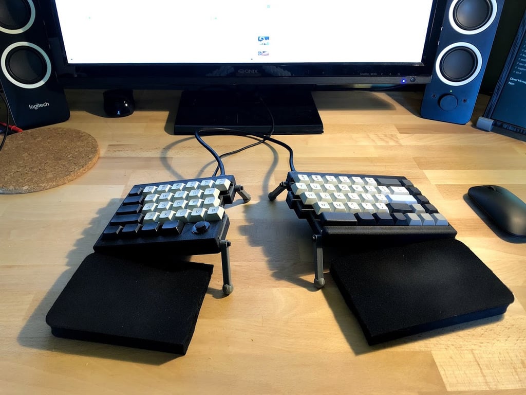
I wanted to build a programmable mechanical keyboard without an unfamiliar layout requiring me to re-learn how to type all over again. There are a few commercial options that _almost_ fit the bill, but the only fully-programmable one isn't quite yet available, and, making things is fun, so why not just do that? You can have that fun, too, if you have [these PCBs fabbed](https://github.com/mohitg11/TS65AVR), buy a handful of cheap parts online, solder a little bit, and print a few parts. This design is a more-refined update to [an earlier case design](https://www.thingiverse.com/thing:3027838). The new features include: * Support for tenting and tilting in a style similar to that of the Ergodox EZ: There are four mounting points -- one on each corner of the keyboard -- onto which you can mount either an "Edge Bumper" or a "Tenting Foot" and "Tenting Leg" set. In my photos above you'll see that I've mounted bumpers on the outside of the keyboard, and leg/feet sets on the inside of the keyboard to slightly tent the keyboard. If you were to instead attach a leg/foot set to each of the mounting points, you could tilt and tent your keyboard in any direction. * A plate that is a separate part from the top and bottom cases: This is a design idea my friend [@fardog](https://www.thingiverse.com/fardog/about) suggested when I was mid-way through printing my fourth or fifth experimental top case design. By having the plate be a separate component, you can much more easily iterate and try out new case designs without needing to desolder and resolder all of your keyboard's switches. * An optional left top case allowing you to mount a PSP1000 joystick for use as a pointing device. This case design omits the key usually used as a spacebar from the left case, but allows you to have a sliding joystick right below your left thumb for use in moving your mouse across the screen without your fingers ever needing to leave the home row. You can find other miscellaneous information about this keyboard in a variety of places including: * @mohitg11's github repo for this keyboard: https://github.com/mohitg11/TS65AVR * This long thread on Geekhack in which @mohitg11 (MOZ) talks through his design process for this board: https://geekhack.org/index.php?topic=79161.0 * A variety of pages on the internet you can find by searching for "TS65" including this Reddit thread that inspired me to build my keyboard: https://www.reddit.com/r/MechanicalKeyboards/comments/6agkuu/ts65_split_65_keyboard ## Parts Needed Minimally, this design requires: * 8x 12mm M3 Machine Screws (Socket Cap) * 8x M3 Square Nuts But depending upon whether you use edge bumpers or tenting legs, you'll need a few extra parts in addition to the above. For each edge bumper you use you'll need an additional: * 1x 12mm M3 Machine Screw (Socket Cap) * 1x M3 Square Nut And for each tenting leg: * 1x 16mm M3 Machine Screw (Socket Cap) * 1x M3 Square Nut ## Firmware The firmware for this keyboard isn't available in QMK's master branch, but you can easily check out the branch `ts65avr` from [my fork of QMK](https://github.com/coddingtonbear/qmk_firmware). You'll need to follow [QMK's instructions for DFU flashing](https://beta.docs.qmk.fm/newbs/newbs_flashing#dfu), and can flash the board by running `make ts65avr:coddingtonbear:dfu`. ## Filament Recommendations Given the varying functions of each part of this keyboard, not all parts should be printed using the same type of filament. You'll have best results if you follow the following filament recommendations: * TPU or any flexible filament: * "Edge Bumper" * "Tenting Foot" * As rigid of a filament as possible (PLA or possibly PETG): * "Left Plate" and "Right Plate" * "Tenting Leg" * Any non-flexible filament you'd like; I used Protopasta's Matte HTPLA in the above photos: * All other components ## Captive Nuts Although the nuts used for for attaching the tenting legs or edge bumpers can be installed after printing, the nuts that hold the case together are captive in the top case models. The details of how you might pause your print at the right time to install those nuts are beyond the scope of these instructions, but the gist of the process is: 1. Turn off interior supports (e.g. "Supports from Build Plate Only") in your slicer, or manually delete generated supports from the areas that will house the top case nuts. 2. Using your slicer's preview, identify the layer number at which the nuts will be covered. 3. Insert a pause command immediately *before* the layer at which the nuts will be covered. This varies somewhat depending on your setup, but if you are using OctoPrint, the command is just `M0`. 4. Start printing your top case. 5. When the print pauses, insert a square M3 nut into each of the four visible slots. 6. Resume your print. ## PSP1000 Details You can obtain a PSP1000 joystick for less than $4.00 on a variety of websites online; search for "PSP1000 Joystick" or "Thumb Slide Joystick". The basic instructions for adding one to your keyboard are as follows: 1. Fully assemble your keyboard except installation of the top left case. 2. Snip off the two mounting tabs protruding from your joystick. In the case designs here, those mounting tabs are not used, and the joystick is instead glued into place. Do not glue this in place quite yet, though. 3. Gather four thin pieces of wire each around nine inches long to use for connecting the joystick electrically. The exact type of wire does not matter much, but you don't have much room inside of the keyboard. What I'd recommend using is thin magnet wire; if you do use magnet wire, note that you can remove the enamel from each end [following these instructions](https://electronics.stackexchange.com/questions/53028/how-to-remove-enamel-from-wire). 4. Position (but do not fasten) the top case into its final position. At this point, you'll notice that the hexagonal slot into which you'll eventually install the joystick has a hole through which you can see the PCB underneath. Thread each of your four wires through that hole and through the mounting hole of the key that would normally be underneath. 5. Solder each wire to one of the pads on the joystick. Take care to note which wire corresponds with which pad on the joystick. Looking at the device from the bottom (with pads on top), the pins are: 1. X Axis 2. +5V 3. Y Axis 4. Ground 6. Refer to the attached image labeled "PSP1000 Connections", and solder the opposite ends of these wires into the places noted. 7. In the keyboard firmware file `keyboards/ts65avr/keymaps/coddingtonbear/keymap.c` uncomment the line reading `// #define ENABLE_PSP1000_MOUSE`. 8. Recompile and flash. 9. Verify that the joystick works. 10. Glue the joystick into place using either a small bit of epoxy or superglue. 11. Finish assembling the case.

Download Model from thingiverse

With this file you will be able to print TS65 Split Mechanical Keyboard Case with built-in Tenting/Tilting and Optional PSP1000 Joystick Mouse with your 3D printer. Click on the button and save the file on your computer to work, edit or customize your design. You can also find more 3D designs for printers on TS65 Split Mechanical Keyboard Case with built-in Tenting/Tilting and Optional PSP1000 Joystick Mouse.