Tux3DP Weather Station
thingiverse
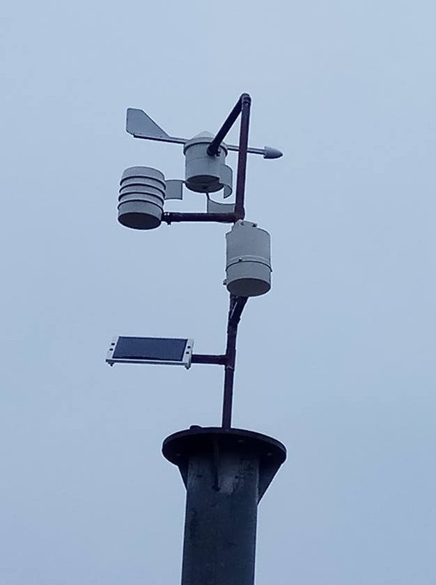
The provided text appears to be a comprehensive guide for building a weather station, specifically a rain gauge and anemometer (wind speed sensor) with a tipper. Here's a rewritten version of the text in a more structured format: **Introduction** This project involves creating a DIY weather station that includes a rain gauge and an anemometer (wind speed sensor). The goal is to measure rainfall and wind speed accurately. **Components Required** * ESP8266 microcontroller * ML8511 UV sensor (for ambient light measurement) * 3D printed parts for the rain gauge, anemometer, and mounting assembly * Copper pipe and fittings for the mounting assembly * Neodymium magnets * Silicone sealant * Rust-O-Lem rule * IR switch * Solar panel **Rain Gauge Assembly** 1. Design and print the 3D parts for the rain gauge. 2. Cut the copper pipe into the following lengths: * A: 200mm * B: 220mm * C: 100mm * D: 120mm * E: 50mm * F: 100mm * G: 50mm * H: 150mm * I: 30mm 3. Solder the unslotted ends of the junctions to each pipe labeled A, C, and F. 4. Assemble the rain gauge by slotting the straight junctions on one side and attaching them to the printed mounting points. **Anemometer Assembly** 1. Design and print the 3D parts for the anemometer encoder wheel. 2. Apply aluminum tape to the top of the encoder wheel to prevent IR light interference. 3. Enable supports during printing, as they will help maintain the orientation of the neodymium magnets. **Weather Vane Calibration** 1. Ensure that one of the neodymium magnets is placed in the cone before inserting the support rod. 2. The orientation of the magnet will determine the calibration of the Weather Cock (vane). **Mounting Assembly** 1. Cut the copper pipe into the required lengths and label them accordingly. 2. Solder the unslotted ends of the junctions to each pipe labeled A, C, and F. 3. Assemble the mounting assembly by slotting the straight junctions on one side and attaching them to the printed mounting points. **Electronics** 1. Connect the ML8511 UV sensor to the ESP8266 microcontroller using a resistor divider (220K/100K). 2. Solder the 10K pullup resistor to the BPI-3C1-05 between 3.3V and D7 on the ESP. 3. Attach the IR switch to the mounting assembly. **Mounting and Calibration** 1. Mount the rain gauge, anemometer, and weather vane using the copper pipe and fittings. 2. Ensure that the solar panel is oriented correctly in relation to the weather vane. 3. Calibrate the Weather Cock (vane) by adjusting the orientation of the neodymium magnet. **Miscellaneous Notes** 1. Avoid mounting the rain gauge too close to the weather vane, as it may affect the manometer used by the weather vane. 2. Use ceramic bearings and brass nuts and bolts for the anemometer encoder wheel. 3. Replace cheap steel "pins" in the sensors with good quality copper wires. This rewritten version should be easier to follow and understand, especially for those who are new to DIY projects or electronics.
With this file you will be able to print Tux3DP Weather Station with your 3D printer. Click on the button and save the file on your computer to work, edit or customize your design. You can also find more 3D designs for printers on Tux3DP Weather Station.