Uconduit Printer Z-offset Adjustment
thingiverse
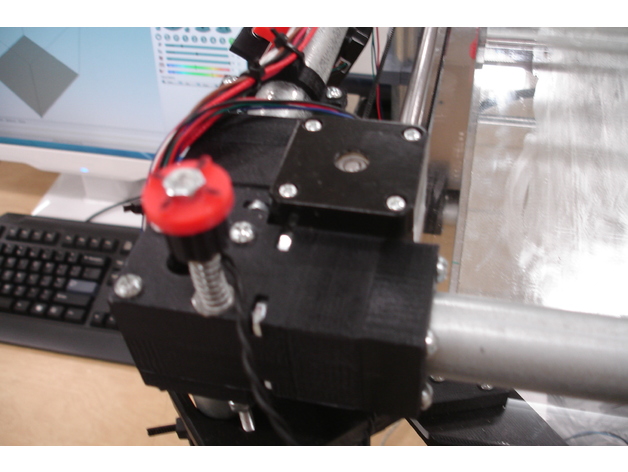
This is a mechanical adjustment for micro-adjusting the Z-offset on the Uconduit H-bot printer. The adjusting knob rod replaces one of the original top corner vertexes bolts, even though this one was installed on the front left leg, it could also be installed on the rear right leg. The actuation comes from a small actuator tab mounted to the Z-axis rod bearing top, so it can use either Z-axis rod. Can easily micro-adjust the height of the nozzle off the bed by turning the adjustment knob 1/8 to 1/4 of a turn. Is great when changing filaments and having to reset the Z offset. After you have used it a while, you will get a feeling for just how far to turn the adjustment. Move it slightly, hit "Z Home" and see the results. Printer Settings Printer: Migbot i3 Resolution: .2 Infill: 30% Post-Printing Assembly The Z-Axis adjustment block rides up/down on the outside of the front left leg (near the top). Inside the sliding adjustment block, two 8-32 nuts with a small section of spring between them help with stability and stop unwanted adjustment movement. The knob should only turn when turned by hand. To assemble: 1) Remove the bolts from the Z-axis bearing block and use those bolts to hold the Z-switch actuator tab in place. 2) Hold the limit switch against the side of the adjustment block and mark where the switch bolt holes should be drilled (compare switch position to the actuator tab position). Then drill the holes for those small mounting bolts. Thread the bolts into the block to make their own threads first. Once the holes with thread are OK, mount the limit switch on the side of the adjustment block. 3) Use a small section of 8-32 threaded rod to move the adjusting block up/down. Assemble the indicator and knob to the top of the threaded rod with nuts on top and bottom of the knob assembly. Put thread locker on nuts to hold them in place. 4) Remove one of the 8-32 machine screw from the top left corner vertexes, add a washer, a spring, another washer to the knob/rod assembly and drop it into place. Put another washer on below the Vertexes block, and then two 8-32 nuts on the threaded rod. Tighten those bottom nuts enough to put a little tension on the spring above the corner vertexes, then lock the nuts together to hold it in place. 5) Turn the adjustment knob to thread the adjustment block onto the end of the 8-32 threaded rod. Keep turning the knob until the limit switch actuates just before the nozzle touched the bed. 6) Add a plastic wire-tie around the adjustment block and the conduit leg to hold the sliding block firmly against the side of that conduit leg. 7) Keep adjusting the new Z-offset adjustment in small increments until the Z looks good. How I Designed This Reasoning Behind the Build: I always had difficulty adjusting the Z-end stop limit switch. It was hard to get it positioned perfectly, then try and hold it in place while tightening up the mounting clamp. The switch moved too easily up and down and all around the 8 mm polished rod. It was too easily bumped out of position. I wanted something that I could easily micro-adjust, and was repeatable. Parts: (1) 6 to 7 inch piece of 8-32 threaded rod (6) 8-32 nuts (3) small washers (2) small 3/4 long springs See the original printer build at: https://www.thingiverse.com/thing:102972 My remix of the original printer build at: https://www.thingiverse.com/thing:2176514
With this file you will be able to print Uconduit Printer Z-offset Adjustment with your 3D printer. Click on the button and save the file on your computer to work, edit or customize your design. You can also find more 3D designs for printers on Uconduit Printer Z-offset Adjustment.