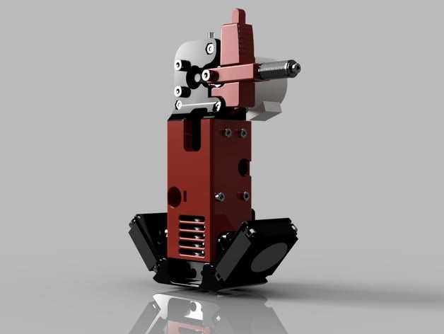
Ultimaker 2 PG35L Direct Drive Extruder for 1.75mm E3D v6 Hotend
thingiverse
A direct drive extruder for the UM2 using a PG35L Nema 17 geared motor. It's light, it's super quiet, and best of all... it prints Ninjaflex! With a 1.75 filament setup, flexible filament would not print on my bowden-based extruders... so this direct drive system was born. Download the source CAD files here: http://a360.co/20NsbBC v2 Update -- Mount/Clamp/Fan Mount changes. See below in Updates Print Settings Rafts: No Supports: Yes Resolution: .2mm Infill: 30% Notes: Print in ABS with 3 shells. Print the latch and idler with more infill (50%). Only the Arm and Mount need support. The extruder body has supports built in. How I Designed This The mounting system is based on lion3's E3D Custom UM Mount. The parts were reinforced and a special cavity was created for the extruder body to slide/lock into place atop of the mount, forming a single body. The extruder body is based on Ultibot's PG35L Micro Extruder. However, I wanted to change the way pressure was applied to the filament against the knurled drive gear to allow for quick removal/reloading w/o having to mess with screws every time. My bowden UM2 printers use IRobertI's Alternative UM2 Feeder and I love the ease of switching filament with the arm/latch system... so I borrowed and incorporated the concept...and a couple parts. ;-) Because the motor is on the printhead, it required me to raise the motor/extruder about 50mm higher to avoid it hitting the rails/A-axis. So a piece of teflon tubing is needed to cleanly feed filament from the extruder to the hot end. My original concern was that this would cause flexible filament to fail to print... but it turns out that it had no affect on the ability to feed flexible filament. Bill of Materials (BOM) Printed Parts Mount Mount Clamp Extruder Body Extruder Idler Extruder Arm Extruder Latch PG35L Heat Sink Fan Duct Vitamins/Hardware 8x M3x6 screws (for blower fans) 4x M3x8 screws (for dual cooling fans mount) 8x M3x14 (or 16) screws (for PG35L duct fan & extruder cooling fan) 4x M3x25 screws 1x M3x20 screws 3x M3x45 screws 8x M3 nuts 3x M4x20mm screws 3x M4 nuts 4x M4 washers 3x 624ZZ Ball Bearings PG35L-048 Geared Stepper motor 35mm Heat Sink MK7 Knurled Drive Gear Compression Spring (1.5" long, similar to this) 30mm fan - 5VDC 4.4cfm 40mm fan - 5VDC 8.15cfm 2x 40mm blower fans - 12VDC 3CFM 4mm OD/2mm ID teflon tubing (2 pieces @ 101mm & 24mm) Assembly Instructions Preparing the printed parts - Most holes can be drilled/cleaned up a bit to allow you to more easily slip screws in... but some holes were designed a bit smaller so a nut isn't required. The following should not be drilled larger: Holes on Mount & _MountClamp that secure the 30mm fan and also the holes that secure the 40mm fan mount. Holes on the 40mm fan mount that secure the blower fans. Holes on the Heat Sink Fan Duct. Bearing Installation - Although not illustrated in the video, use an M4 washer on each side of the bearing on the Extruder Idler during installation. It's not required, but helps keep the bearing secure from shifting. Compression Spring - Use a heavy duty compression spring that's about 1.5" (38mm). Use a M5 and M4 washer on each side of the spring (depending on your spring's diameter) to compensate for the diameter difference between spring and M3 screw. 40mm Dual Cooling Fan Mount - I used Kapton (teflon) tape along the bottom area that is exposed to the hotend aluminum block. 3-4 layers should be enough to assist in keeping the direct heat off the plastic. I've used this method successfully with other custom fan shrouds used on my other printers. Electronics PG35L-048 wiring - On the Ulti-controller, looking at the E1 port (E2 port will be on the left of E1), the wiring colors are (left-to-right): Yellow, Orange, Brownish-Gray, Black. Before Running Motor Decrease the milliamps to 600ma for the extruder motor. [Main Menu] --> [Maintenance] --> [Advanced] --> [Motion Settings] --> [Current E] --> 600ma The 2 5VDC Cooling Fans - Both of these fans (30mm and 40mm) will be wired in parallel (black-to-black and red-to-red) and then connected to the normal 5VDC output on the board. It's very important to use the heatsink and fan duct on the PG35L stepper or the motor will overheat. Note: Both of these fans are high CFM output, so they're the loudest thing about the entire printer. It's possible to use the unused 24V PWM output (hotend 2), by stepping down the voltage to 5v w/a voltage converter and then updating the firmware to use that pin in correlation to the hot end temp to turn on the fans. The Marlin firmware already supports this feature. Dual 40mm Blower Fans - These fans put out an incredible amount of air. Some would argue it's more cooling than you need... maybe... but they're more quiet than 30mm fans and I wanted to try a design with blower-style fans. They need to be wired in a serial connection (just like the original UM2 fans), that is red wire of one fan to black of the other fan. Remaining black and red wires, from each fan, are run to the controller's FAN output Firmware Changes The following values need to be changed in the configuration.h file of the Ultimaker2 Marlin firmware. Note: The default firmware has the MAX positions all set at 230 but that actually exceeds the limits on the official UM2 Y & Z axis. With this design we lose about 15mm on the X axis and 10mm on the Z, as the E3D hot end is much larger than the default UM2 hotend. #define X_MAX_POS 213 #define Y_MAX_POS 220 #define Z_MAX_POS 215 //increase if your z axis is longer (e.g. UM2 Extended) #define DEFAULT_AXIS_STEPS_PER_UNIT {80.0,80.0,200,800} //for MK7 gear #define DEFAULT_MAX_ACCELERATION {9000,9000,100,500} #define DEFAULT_EJERK 1.0 // (mm/sec) #define FILAMANT_BOWDEN_LENGTH 50 #define END_OF_PRINT_RETRACTION 1.5 //defaults to 20mm * steps per unit will be different for MK8 drive gear. Ultimaker Profile (or Slicer) Changes If you use Cura, you will need to update your retraction settings on the UM2. If you use Simplify3D, you'll update retraction in your S3D profiles. Retraction Distance 1mm Retraction Speed 5mm/s Additional Changes If you use Simplify3D, you will want to make the following changes in your profiles: Under Scripts --> Starting Script. Remove the following line to prevent an override of amps to the extruder motor: M907 E1400 ; increase extruder current Change the following items, so they don't extend beyond your X-axis range. This example works with the X_MAX_POS setting above: G1 X190 Z0 F9000 ; pull away filament G1 X210 F9000 ; wipe Updates Update v2 The Mount/Clamp was modified to wrap the floor around the E3D heatsink in an effort to reduce the E3D cooling fan's flow from getting to the print bed. I noticed with ABS plastic, where I don't use print cooling fans, that too much air was hitting the print, cause curling. Holes moved for the 40mm Fans Mount. The 40mm Fans Mount has been updated to narrow the opening around the nozzle. Also moved the mounting brackets higher so you can remove the mount with the fans still attached. This makes maintenance easier. Update v3 Updated stepper motor milliamps from 1100mA to 600mA. Turns out I was really lucky with my first build. But when I decided to build one for my other UM2 clone, I killed the new motor by running too many amps to it. I got about 8 hours of printing from it before it died. Update v4 Thanks to user jffry7, I have updated the firmware changes to include END_OF_PRINT_RETRACTION. The previous value of 20mm was meant for bowden tubes and caused him a lot of trouble printing PLA.
With this file you will be able to print Ultimaker 2 PG35L Direct Drive Extruder for 1.75mm E3D v6 Hotend with your 3D printer. Click on the button and save the file on your computer to work, edit or customize your design. You can also find more 3D designs for printers on Ultimaker 2 PG35L Direct Drive Extruder for 1.75mm E3D v6 Hotend.