Ultimate Dremel Tool Bit Holder and Organizer
prusaprinters
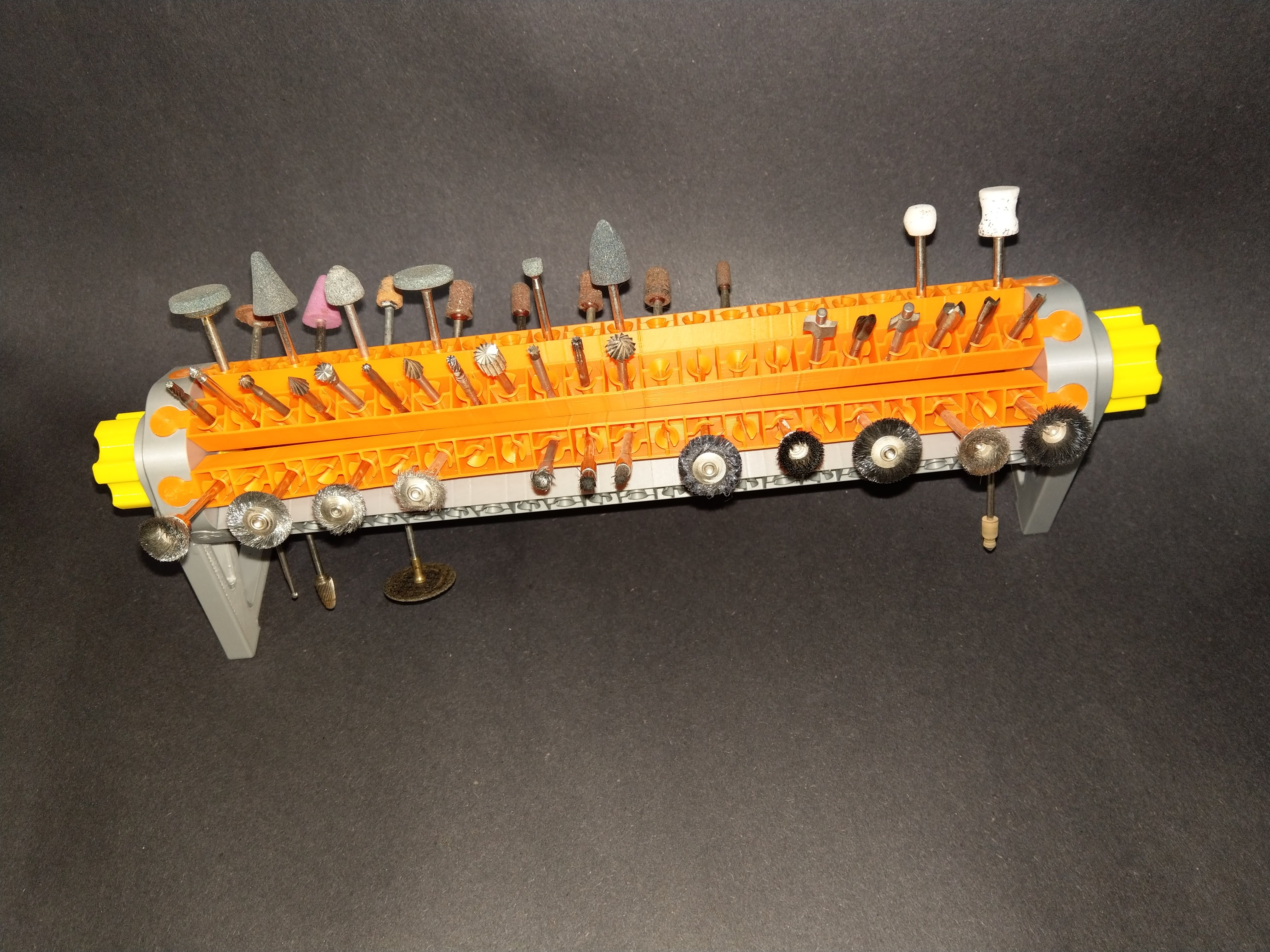
<p>If you have owned a Dremel type tool for any length of time, you will likely have accumulated a large number of tool bits. These come not only in many different types, but also in several different shank sizes (see below).</p> <p>Dremel Shank Sizes (and labeling system) :</p> <p>No rings 1/8in .125in 3.18mm<br/> One ring 1/32in .032in 0.79mm<br/> Two rings 1/16in .063in 1.59mm<br/> Three rings 3/32in .094in 2.38mm</p> <p>Up until now, I have used a block of wood with multiple holes drilled in it, together with a miscellaneous collection of boxes. My goal with this project was to create a tool bit holder that would meet these criteria :</p> <ul> <li>hold a large number of tool bits</li> <li>hold bits of different shank sizes</li> <li>provide for organization and ready access</li> <li>take up a minimal amount of space</li> <li>can be used in a variety of conigurations : desktop, wall or under-shelf mounted, or pegboard mounted</li> </ul> <p>After much experimentation, I settled on the design presented here. The rotary arrangement saves space, and has the additional advantage of making the tool bits easier to view and select. This holder uses 8 "arms" held in a rotating frame. Each arm consists of a number of "cells" - each cell holds one tool bit. To accommodate tool bit collections of varying sizes, I have provided for arms with different numbers of cells - simply choose the size that fits your needs. The available sizes (and corresponding tool bit capacities) are shown below:</p> <p>Cell Approx<br/> Width OAL Capacity<br/> cm in (tool bits)<br/> 10 20 8 80<br/> 16 27 11 128<br/> 20 32 13 160<br/> 22 35 14 176</p> <p>Note that the indicated capacities are nominal, as some tool bits may require wider spacing (cutting disks, for example); I suggest you plan accordingly.</p> <p>Each cell contains a "spring holder" which consists of two conical pieces which are attached to the sides of the cell but are not attached at the bottom. This design allows each half to flex sideways, and the conical shape adapts to differing shank diameters.</p> <p>The 22 cell holder is the largest possible size for my printer (and probably the largest practical size as well). I elected to print this size, which is shown in the photos. I printed two of the bitholder arms in different colors - I will use these to sort by shaft size. Another option would be to print multiple smaller holders.</p> <p>In addition to the basic holder for use on the desktop, I have provided adapters for other mounting options. These adapters attach to the bottoms of each frame leg with three M3x10 self tapping flat head screws (or #4 equivalent). The mounting adapters provided are as follows :</p> <ul> <li>plate : Use these to attach to a wall or the under-side of a shelf with an M4 flat head wood screw (or #10 equivalent).</li> <li>PegPlateH : Use these to mount the holder horizontally on pegboard.</li> <li>PegPlateV : Use these to mount the holder vertically on pegboard.</li> </ul> <p>Directions for assembly are given in the Print Instructions.</p> <p>The OnShape 3D CAD files for this are here :</p> <p><a href="https://cad.onshape.com/documents/4077388df02afe1449d1c70b/w/488fd7ad6501d5980b5b018e/e/283953ee66139b2444959f32">https://cad.onshape.com/documents/4077388df02afe1449d1c70b/w/488fd7ad6501d5980b5b018e/e/283953ee66139b2444959f32</a></p> <h3>Print instructions</h3><p>PRINTING</p> <p>Print in PLA using the 3mf files provided; otherwise :</p> <ul> <li>stands : 3 perimeters, 15% rectilinear infill</li> <li>wheels : 2 perimeters, 10% rectilinear infill; print with bitholder slots facing up</li> <li>handles : 2 perimeters, 20% rectilinear infill; print with screw facing up</li> <li>bitholders : 2 perimeters, 25% rectilinear infill; print with flat side down; rotate longer holders to fit build plate</li> <li>brace : 2 perimeters, 15% rectilinear infill</li> <li>adapter plates : 4 perimeters, 25% rectilinear infill</li> <li>hooks : 5 perimeters; use brim; print on side</li> </ul> <p>The required parts are as follows :</p> <ul> <li>Handle : 2 required; this is the knob that screws into the wheel</li> <li>Wheel : 2 required; this is the part that holds the bit-holders</li> <li>Bitholders : 8 required; pick the size desired and print all 8 in the same size. Multiple colors can be selected to help with bit organization.</li> <li>Stand : 2 required; this is the frame that holds the handles and wheels</li> </ul> <p>Optional parts are as follows :</p> <ul> <li>Brace : recommended for prints using the longer bitholders</li> <li>ScrewPlate : 2 required; use these for screw mounting</li> <li>PegPlateV and peg sets : 2 required; use these for mounting to pegboard vertically</li> <li>PegPlateH and peg sets : 2 required; use these for mounting to pegboard horizontally</li> <li>Peg hooks : You will need these if you are mounting the holder on pegboard.</li> <li>Bitholder test block : this is a single "cell" which can be printed for test purposes.</li> </ul> <p>ASSEMBLY</p> <blockquote><blockquote><blockquote><p>MOUNTING PLATES</p> </blockquote> </blockquote> </blockquote> <p>I recommend attaching mounting plates (if desired) before starting the main assembly.</p> <p>Print out two sets of mounting plates for the type of mount desired. Each plate attaches to the bottom of a stand frame with three M3x10 flat-head self-tapping screws (or #4 equivalent).</p> <ul> <li>ScrewPlate : may be mounted with the mounting hole inside or outside the frame, as desired. Use an M5 wood screw (or #10 equivalent) for mounting.</li> </ul> <p>The adapter plates for mounting on pegboard require you to add "hooks" to the adapters. The 3mf file provided will print out all the required hooks (with some extras just in case).</p> <p>The hooks are a tight fit, so be sure to trim off any flashing left over from the printing brim. To insert the hooks, rotate the hook 90 degrees from its final position and force the "foot" into the slot (this will be a very tight fit); use needle-nose pliers to assist with this. Once the hook is fully in the slot, rotate it into its final position - you will feel some initial resistance to rotation until the hooks "pops" into place. See the photos for how these should look (note I only used two screws in the photos, just for testing purposes; I recommend using all three for final assembly).</p> <ul> <li><p>PegPlate H : Use these two plates - one for the left side and one for the right, to mount horizontally on pegboard. Insert a curved hook into each upper slot, and a straight hook into each lower slot. Adjust the hooks horizontally in the slots to fit your pegboard hole spacing.</p> </li> <li><p>PegPlate V : Use these two plates - one for the top (rectangular) and one for the bottom (rounded) to mount vertically on pegboard. Insert two curved hooks into the upper plate. Insert one straight hook into the lower plate. Adjust the hooks horizontally in the upper plate, and vertically in the lower plate, to fit the hole spacing in your pegboard.</p> </li> </ul> <blockquote><blockquote><blockquote><p>MAIN ASSEMBLY</p> </blockquote> </blockquote> </blockquote> <p>Start the assembly by inserting each handle through a stand frame. The wheels have raised ridges to provide some friction when turning; I recommend adjusting the friction level by gently scraping each ridge with a razor knife until there is just slight friction. I also applied a dab of grease before final assembly.</p> <p>With the handles inserted into the frame stands, screw each wheel onto a handle; note the openings on the wheel must be oriented away from the frame. Tighten the handles firmly but be careful not to over-tighten or parts may crack.</p> <p>IMPORTANT! : Before inserting the bit-holders into the wheels, insert a 1/8" (3mm) tool bit into each opening. The reason for this is that there is likely to be some minor bonding of the "springs" to the bottom of the cell; inserting a tool bit breaks this bond and makes bit insertion easier. As you insert a tool bit for the first time, you may hear a "breaking" sound as the spring comes loose; this is normal.</p> <p>Once the bit-holders are "broken in" (literally!), insert each bit-holder into a wheel opening. The bit-holders are a friction fit - push them all the way in by squeezing from opposite sides of the wheel; I also used a wood block to help gently seat the holders into place. If you are screw-mounting the assembly, first install four of the bit-holders on opposite sides of the wheels, and then use the partially assembled holder as a guide to mark the location of the mounting holes; you can then mount the partial assembly (to allow for screw-driver clearance); if necessary mark the hole locations and remove the handles in able to screw down the frame stands - then reassemble. If you are using the brace, insert it now (insert it sideways and twist into place in the middle) before adding the remaining bitholders.</p> <p>This completes the assembly of the bit holder.</p>
With this file you will be able to print Ultimate Dremel Tool Bit Holder and Organizer with your 3D printer. Click on the button and save the file on your computer to work, edit or customize your design. You can also find more 3D designs for printers on Ultimate Dremel Tool Bit Holder and Organizer.