Ultimate PCB and IC Vise – Version 4 - Printable Vise for Small Electronics
thingiverse
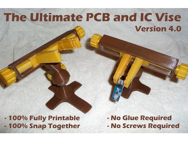
Project : This 100% fully printable PCB and IC Vise project is my personal remix to the original “Fully Printable PCB Vise” by sneakypoo, with some mods made by other people, and a few of my own personal mods. This vise is PERFECT for holding Printed Circuit Boards (PCB), Integrated Circuit (IC) boards, and/or any other small electronics. The vise is useful for soldering or working with these circuit modules. The vise is 100% printable and should be easy to print on most 3D printers with a 200mm X 200mm print bed. Most importantly, this vise can be assembled without any glue or screws - you just snap the vise together and it is ready to use! I should also mention that this vise is NOT designed to grip, compress, or squeeze an object with any real amount of force – the vise is really only strong enough to hold the items in place while you’re working on them. Also, there are some important items to consider when building this vise, so be sure to see the notes I’ve provided below. Print Settings Printer Brand: Prusa Printer: Prusa Steel Rafts: No Supports: No Resolution: 0.2 mm Infill: 10 Notes: Printing Notes and Suggestions: After printing all of the parts, I typically use a small file on any rough edges and to smooth the parts the rub against each other. This typically includes a little smoothing of the Jaws (the parts that slide inside the Bracket), the inside of the Bracket part, and the Drive Screw part. Screwing the Jaws onto the Drive Screw will be very tight at first (depending on which drive screw you choose) and I highly recommend working the jaws on and off the entire screw first until it is completely smooth, before trying to put the Jaws and the Drive Screw into the Bracket piece. Also, I would make sure that the jaws slide back and forth in the Bracket, because trying to put the Jaws assembled on the Drive Screw into the Bracket part and be a little tight, and if it’s too tight, it will be very difficult to get out again without breaking the Drive Screw. The Drive Screw – this is probably the single toughest part of the project to deal with and I have included four different Drive Screw designs with this version of the vise project. Be aware that the original Drive Screw was designed to be purposefully tight and is impossible to print standing up (on my cheap Prusa i3 3D Printer at least). So, the v2 Drive Screw design has the screw laid down on its side and made one side flat to make it possible to print. However, using the v2 screws, I still had to do A LOT of sanding and filing to get it to work smoothly in the vise. So I also created the v3 Drive Screw design with two flat sides and two treaded sides and it was much easier to get working. And I also made a v4 Drive Screw with four flat side and only treading on the corners which is really, really easy to work with. Also, regardless of which Drive Screw version is used, I had to file the ends a little bit to get the screw to fit into the Bracket part and move smoothly. You can print two Thumb Knobs and skip the end cap if you want knobs on both sides of the vise. If you decide to use an end cap, instead of two Thumb knobs, you may want to glue the end cap into the drive screw, because it has a tendency to get loose and fall out after prolonged use. If you want to print the vise in two colors, the first five parts can be one color, and the last four can be a second color to give your vise a cool, two-tone look! STL Files and Parts List: The following is a list of all of the files that are included in with this distribution of the Ultimate PCB Vise: PCB_Vise_v4_Part1_Left_Jaw.STL PCB_Vise_v4_Part2_Right_Jaw.STL PCB_Vise_v4_Part3_Lock_Screw.STL PCB_Vise_v4_Part4_Stopper.STL PCB_Vise_v4_Part5_Thumb_Knob.STL PCB_Vise_v4_Part6_Screw_v1.STL PCB_Vise_v4_Part6_Screw_v2.STL PCB_Vise_v4_Part6_Screw_v3.STL PCB_Vise_v4_Part6_Screw_v4.STL PCB_Vise_v4_Part7_Bracket.STL PCB_Vise_v4_Part8_Swivel.STL PCB_Vise_v4_Part9_Base.STL PCB_Vise_v4_Part9_Base_LongLeg.STL Notice that there are four “Part 6” (Drive Screw) files included, the “Part 6 Screw v1” file being the original STL file included with this project, but is the hardest to print and use. The “Part 6 Screw v2” file has ONE side cut off and is printed on its side for much easier printing, but it is still pretty tight – I had to file down the teeth to get it to work with my vises successfully, it was just too tight otherwise. The “Part 6 Screw v3” file has TWO sides cut off and is easy to work with without too much work on the jaws. And finally, the “Part 6 Screw v4” file has all FOUR sides of the screw cut off, and is essentially a square with screw teeth on the corners. The v4 screw is very easy to work with, I didn’t have to hand file it at all. Also note that there are two “Part 9” (the Base piece) STL files included in the package. The “Part 9 Base” file has the original base created for the vise. The “Part 9 Base Long Leg” file is a mod that makes the vise much more stable, which I recommend. Post-Printing Simple Assembly Instructions: Print one of each part of the Vise included in the parts list of STL files. All parts should be easily printable at 0.2mm height with a 10% infill. For the Drive Screw and Base pieces, I suggest 40% infill as there is a lot of stress on that piece. You can print two Thumb Knobs parts and skip the End Cap part if you want knobs on both sides of the vise, which I recommend. Snap together all the parts and away you go!! Detailed Assembly Instructions: Before Constructing the Vise, be sure to screw the Jaws (Part 1 and Part 2) on to the Drive Screw (Part 6) and make sure both Jaws screw smoothly all the way along both sides of the screw. This may require you to screw the Jaws on and off several times before it is smooth enough. Also, filing the Drive Screw will help a lot here if it’s really tight. Once the Jaws screw easily and smoothly, roll the both all the way out to each side of the screw, so that the ends of the Jaws are flush with both ends of the Drive Screw. Then screw both Jaws pieces inward uniformly for a few full turns of the screw. This is to ensure that the Jaws are positioned correctly on the drive screw. Take the Drive Screw assembly and snap it into the Bracket (Part 7). It should fit in without too much work, so if it doesn’t go in easily, I recommend filing down the end of the screw and the inside ends of the Bracket part, to ensure everything is nice and flat. Then insert the Thumb Knobs (or Thumb Know and End Cap) through either end of the Bracket into the Drive Screw. Note that the Thumb know has a plus sign shape to lock into the screw, and should fit all the way in and snugly into the ends of the Drive Screw. The Thumb Knob should also sit properly in the Bracket, which will keep the screw in place. The place the Swivel Joint piece (Part 8) on top of the Base piece (Part 9). The Swivel part should mount easily and be able to move all the way around the ball mount on the Base. Use the Lock Screw piece (Part 3) to tighten the Swivel to the Base. Snap the Bracket assembly into the top of the Swivel Joint part. The Bracket should snap in very tightly and should not move once it has been snapped into the Swivel. If these parts are too loose when connected, I would recommend using a dab of glue to hold these parts together. Your new vise is now assembled and ready to use! Project Credits I’d like to give credit and my utmost respect for these STL designs to all the people that made this project possible. Credit for this work should go to the following people and entities: To Robert (Sneakypoo - http://www.thingiverse.com/sneakypoo/about) for Robert‘s original PCB Vise design: http://www.thingiverse.com/thing:21357. To Sam Wong (Sam0737 - http://www.thingiverse.com/sam0737/about) for Sam’s Dovetail Bracket Mount design: http://www.thingiverse.com/thing:68619. To Stephen Froese (SFroese10 - http://www.thingiverse.com/sfroese10/about) for Stephen’s Extended Foot Base design: http://www.thingiverse.com/thing:1303437. To Geoffrey L. Griffith (Me – GeoffreyG - http://www.thingiverse.com/GeoffreyG/designs) for Geoffrey’s modified Drive Screw designs and updating this project: http://www.thingiverse.com/thing:2069988 And last, but most importantly, Thingiverse.com for being so incredibly amazingly AWESOME and hosting this unending repository of knowledge and product designs for the world to use 100% free of charge. Your contributions are the most important in this great endeavor and I’m eternally grateful for the services you provide! Project Goals I decided to recreate the PBC Vise project to try to get it to a point where I’m 100% satisfied with the vise. This included the solving the following problems: To make the vise 100% fully printable and not require any glue or screws, To include some of the useful modifications for this project, To include my own personal modifications to this project, To make it much easier to print and assemble the vise, and To ensure a complete package of files with this distribution of the vise. As such, I’ve included several upgrades available on Thingiverse.com for this vise, as well as created several of my own drive screw variants, to make this vise as easy to print and use as possible. The original vise design required the Bracket to be glued to the Swivel Mount, which was not optimal and there was a snap-in dovetail mod that was better for assembly purposes, which seems to work very well. There was an “Extended Foot” base design that was a very good upgrade too, because it makes the vise much more stable. I’ve included all of the STL part files in this distribution, because so many of the other distros out there only had specific parts or were missing important pieces of the vise altogether. And finally, I’ve numbered each of the parts of the vise to make it as easy as possible to know which parts are which, and which pieces can be exchanged for the different modifications. Project Revisions and Change Log 2017/01/29 – Version 4.0 – The new Ultimate PCB and IC Vise version 4 project was assembled and posted to Thingiverse.com.
With this file you will be able to print Ultimate PCB and IC Vise – Version 4 - Printable Vise for Small Electronics with your 3D printer. Click on the button and save the file on your computer to work, edit or customize your design. You can also find more 3D designs for printers on Ultimate PCB and IC Vise – Version 4 - Printable Vise for Small Electronics.