USB powered RT-qPCR module
thingiverse
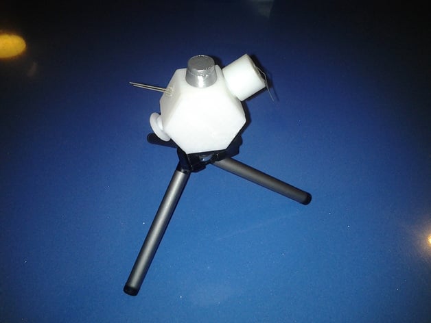
Difficulty level: Advanced (see disclaimer at end). I've listed the parts and approaches that I've used, and my results so far. I think the project is at the point where others might find it worth considering for more advanced setups. It grew out of an Instructable: http://www.instructables.com/id/Coffee-Cup-PCR-Thermocycler-costing-under-350/ You might also look at the BioHacking explanation webpage at http://en.wikipedia.org/wiki/Biohacking and the brilliant work at Open PCR http://openpcr.org/ The idea is to explore a 3D printed enclosure for this module. The possibilities seem almost limitless. I can print new designs for enclosures as fast as I can CAD them up. Hope this information helps in your approaches. This project seeks to configure a 3D-printed, USB powered, remotely accessed, disposable, low cost - Real Time Quantitative PCR (qPCR or RTPCR) module. Background: Polymerase chain reaction (PCR) has revolutionized broad areas of forensics, medicine, biology and field research. Unfortunately Real Time (RT) PCR platforms which are able to track and display the amplification of DNA samples during a PCR procedure remain prohibitively expensive. The development of a 3D printed, low cost USB powered remotely accessed system for under 220$ would be a tremendous advantage for research, medicine and education. What makes this project interesting?: 1.Broad range of applications with significant impact on education and research. 2.Novel 3D printable Design features 3.Combination of low cost technologies 4.Providing access to Research technology Ruggedized system for field research A unique aspect of this project is that the development of a low cost portable RT-PCR module would span many levels of many types educational application. These range from training young scientists in high school programs, through affordable teaching capabilities in molecular and biological science laboratories in graduate school settings, to postgraduate research laboratories and include ruggedized and portable field research applications. The goal is to provide a portable USB powered RT-PCR module at a cost below 220$ and to provide this configuration with educational content, possibly in association with a biopharmaceutical corporation. The objective is to provide this system not only at an affordable cost for academic programs but also to “ruggedize†the module for use in biomedical, environmental and field research settings. Ideally the unit could be run with a parallax Basic stamp module, an LCD screen and a minty boost power supply. Initial tests have demonstrated acceptable thermal cycling (even without styrofoam insulation) and properly timed light level monitoring based on thermal cycling. The Labview graphical software platform makes it easy to tweak the capabilities and develop high end user interfaces. I'm currently tweaking the Light sensing keyed on Temperature reading in a separate graph. Disclaimer: This is my experience. I'm not telling you what to do, just what I did. If you try this and brick your computer, then its on you. No seriously, I mean that part. This project is intended to explore the capabilities of low cost RT PCR on a 3D printed platform and is not intended for diagnostic or field research use. It is only intended for educational, instructive or illustrative uses. Instructions Current project phase: Project is a "work in progress". Currently writing Light level sensing in Labview, based on cycle temperature with separate light level graph and data logging to txt file. Would also like to find a more sensitive light sensor, maybe a PMT (photo multiplier tube) but want to stay with the USB power only challenge. Might use a phidget light sensor. One limitation is that this is a single sample only module. I might like to make it a four sample system. With 3D printing that's a breeze. Instructions and Parts list: 1) Assemble electronic parts. 2) Write control program in LABVIEW (or Basic stamp module with LCD screen) 3) Print out a 3D housing/Enclosure for the module (Hexagonal box with lid). 3) Drill hole for LED, for sample tube in top and hole for the Band pass filter holder to sit in. The band pass filter sits over the Photoresistor, between the sample and photoresistor. 4) Do some cool experiments Notice that when a 0.2 ml PCR tube sits in the top sample hole, the LED light shines onto the tube at and angle and that the BAND pass filter is out of the direct line of the LED beam. The internal angles of the hexagon are 120 degrees. These angle converge on the sample tube while the Minco Thermofoil heaters are on the front and back sides of the enclosure. Parts List: Temp sensor [1051_2 - PhidgetTemperatureSensor 1-Input 60$] Thermocouple [3109_0 - TPK-01G Bead Probe K-type (-50°C to +450°C) 12$] Heaters [Minco heaters low voltage [MINCO HK5561R37.4 L12B 0021 two from Ebay 25$] Cables [old USB cables from previous projects - free] Relays [3053_0 - Dual SSR Relay Board 30$] Photoresistor [ bag full from ebay 2$] Phidget voltage divider [1121_0 - Voltage Divider 7$] adjustable sensitivity Band pass filter [Edmund optics Filter INT 532 or 535 nm 11.80 mm Diameter 25$] Control program [Labview] 2/2/2 2 digital in, 2 digital out, 2 analog in board [1011_0 - PhidgetInterfaceKit 2/2/2 50$] LED [emits the wavelength for SYBER green fluorescence (Aqua 497) 10$ for a few]. Remember you could also use an infrared LED, but might be some secondary peaks. Total cost for parts 50+25+1+30+25+12+60+2+10=215$ (not counting LABVIEW or 3D printer) If you don't have either a 3D printer or Labview graphical programming platform then consider using an Altoid Minty boost as a power supply (good for 30 thermal cycles) and a Parallax Board of education (Basic stamp) with an LCD screen. The programming is straight forward just keep your "Big Picture" overview in mind and draw what you want the BASIC program to do on a black board. Then take it one part or step at a time and test each capability. Its really not as complicated as it seems. Just remember to turn on the LED and to take a Light reading at the same temperature on the way up a temp curve and on the way down, to see the differences. Disclaimer: This is my experience. I'm not telling you what to do, just what I did. If you try this and brick your computer, then its on you. No seriously, I mean that part. This project is intended to explore the capabilities of low cost RT PCR on a 3D printed platform and is not intended for diagnostic or field research use. It IS intended for educational, instructive or illustrative uses.
With this file you will be able to print USB powered RT-qPCR module with your 3D printer. Click on the button and save the file on your computer to work, edit or customize your design. You can also find more 3D designs for printers on USB powered RT-qPCR module.