USB WYE - Power Only
thingiverse
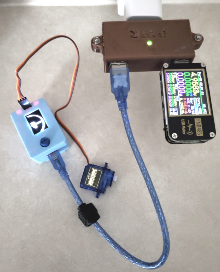
USB WYE - Power Only This is a power-only USB wye adaptor. Yes, I know. They sell USB splitter cables for a song, but where's the fun in that? The data lines are not connected. The utility of this device is simply to power or charge two USB devices from one USB supply port. Current limitations of the port supplying the power should be observed. I recommend not supplying this device with any kind of smart charger as some of these depend upon the data lines for communication with the device being charged. The 3D printed parts consist of three spacers for the USB connectors (two flavors), a mount for the LED that functions as a power indicator and a two-part case. The circuit board is a common 30 mm X 70 mm project board and the box is sized for that particular board. The circuit board is captive within the case; hold-down screws or glue were not used. I used 26 gauge stranded wire; 28 gauge would probably be OK. 30 gauge stranded wire was used for the LED leads. NOTE: Some of these instructions are unnecessarily detailed for those experienced with electronics. I added the extra detail to help more inexperienced builders make their way through this. - - - - - Bill of materials: 3D Printed Parts: - Board Spacer - USB Female, qty 2 - Board Spacer - USB Male, qty 1 - LED Mount, qty 1 - Base, qty 1 - Cover, qty 1 30 mm X 70 mm PCB Project Board, qty 1: https://www.amazon.com/Double-Prototype-Bread-Tinned-Universal/dp/B0C2JLDHYJ/ref=sr_1_11?crid=2BNA8JSM9I44S&keywords=70+X+30+pcb&qid=1687201871&sprefix=70+x+30+pcb%2Caps%2C102&sr=8-11 USB-A Male to DIP Breakout Board Adapter, qty 1: https://www.amazon.com/dp/B09LC8WQCD?ref=ppx_yo2ov_dt_b_product_details&th=1 USB-A Female to DIP Breakout Board Adapter, qty 2: https://www.amazon.com/dp/B07W7XMV3W?ref=ppx_yo2ov_dt_b_product_details&th=1 Male pin header, 4 pins, qty 3: https://www.amazon.com/MCIGICM-Header-2-45mm-Arduino-Connector/dp/B07PKKY8BX/ref=sr_1_3?crid=274AMEXVHI1JF&keywords=male+pin+header&qid=1687202167&s=electronics&sprefix=male+pin+header%2Celectronics%2C114&sr=1-3 - NOTE: These come in long breakable strips. The desired length of header can be snapped off a longer strip. M2.5 X 10 mm machine screw, Allen or Phillips head, qty 2 M2.5 hex nut, qty 2 M2.5 flat washer, qty 2 Green LED, 3 mm, qty 1 1.8K ohm, 1/8 watt resistor (brown/gray/red) Wire Solder Heat shrink Cyanoacrylate gel - - - - - Assembly: IMPORTANT: For the USB ports, note from the images which side will face up on the large board. The male USB port is installed with the pin lettering facing down. Make a note of which pins are VBUS and GND before soldering the male USB port to the main board because the labeling will no longer be visible. The finished board will not fit in the case if the male USB port is installed incorrectly. 1) Prepare the three USB port sub-assemblies: - Glue the 3D printed USB spacer pieces to each of the USB port PCBs with cyanoacrylate gel on the downward facing side of the small PCB. These spacers will lie between the USB port PCBs and the main board. The pegs on the spacers will mate with the holes in the small PCBs. - Solder the three 4-pin headers to the small USB port circuit boards. Solder these with the plastic pin header body on the same side of the small boards as the 3D printed spacer pieces. The long pins of the pin headers go through the USB port boards, pointing up after assembly. The short pins will go through the 30 mm X 70 mm PCB and be soldered in the next step. Only the two outer pins of each 4-pin header need to be soldered. 2) Solder the three USB port sub-assemblies (each consisting of USB port; spacer; pin header) to the large PCB. Note the locations carefully or the case won't fit - see image and details in the sub steps immediately below. Optionally, you may use cyanoacrylate gel on the 3D printed spacer to glue each subassembly to the large PCB in the correct location before soldering. Only the two outer pins of each 4-pin header need to be soldered. - The two female USB port pin headers should be in the last pin hole at each end of the large PCB, in the sixth row of holes in from the edge of the board where the female ports face. See image. - The male USB port pin header should be in exact center of the large PCB (ten empty holes on each side of it) in the fourth row of holes in from the edge of the board where the male port faces. See image. 3) Prepare the indicator LED sub-assembly. - Solder the 1.8K ohm resistor to one of the LED leads. The resistor has no polarity and either end of it can be soldered to either LED lead. The LED itself, however must be connected properly to work. The long lead is positive; the small flat on the edge of the LED flange indicates the negative lead. - Solder short (~ 40 mm) pieces of 30 gauge wire to the remaining unused ends of the LED and the resistor and heat shrink the connections. - Insert the LED into the hole in the 3D printed LED Mount from the center, pushing it all the way to the shoulder. Secure the LED in the LED Mount with cyanoacrylate gel on the inside surface. 4) Wire the three USB ports; all three USB VBUS pins connected together; all three USB GND pins connected together; wires from the LED should be tied to these connection points as well (LED positive to VBUS; LED negative to GND), observing the correct polarity for the LED. Use heat shrink where appropriate. Caution: DO NOT glue the LED Mount to the circuit board. It will be difficult to place it accurately so that the hole in the cover fits over it if it is glued. Instead, let the LED Mount sit in place loosely so it can float around and assume the proper location once the LED is in the hole in the cover. Once the cover is in place with the LED in the hole, the LED Mount can't go anywhere. 5) Install two M2.5 hex nuts in the pockets in the lower case ears. 6) Place the assembled circuit board in the lower case. 7) Install the cover with two M2.5 machine screws and flat washers, assuring that the LED is in the hole in the cover. - - - - - Printing Notes: Nozzle: 0.3 mm (0.4 probably OK) Layer Height: 0.1 mm Shells: 0.8 mm Infill: 12% Material: PLA Printing Orientation: - Print Base upright; print Cover upside down. - Print LED Mount with hole on the bed. Supports are not needed; the sagging will be on a surface where it won't matter. Supports: Supports from the bed are needed for Case and Cover because of the ears.
With this file you will be able to print USB WYE - Power Only with your 3D printer. Click on the button and save the file on your computer to work, edit or customize your design. You can also find more 3D designs for printers on USB WYE - Power Only.