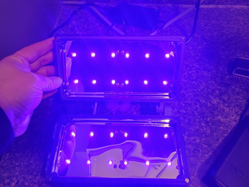
Uv Sterilizer
thingiverse
I have included the Arduino sketch and the PDF templates to cut out the mirrors in the files for those who need them. How to Sanitizer 1. As we discussed before. The design phase has been completed so we need to begin the construction phase. 2. Select your 3d printer filament and go to your slicing software. Load the files and slice to the settings appropriate to your printer and filament. 3. Once the printer has begun it’s printing process for the lid. Gather all your supplies a. 1) Arduino Nano b. 1 ) solid state DC Relay c. 1) Micro USB Cable d. 4) 5mm diameter magnets 3mm thick e. 24) 250nm to 280nm led 5v (if yours are 3 be sure to figure out what resister gets you to the right voltage. (these should be in this wavelength; this is the wavelength that causes DNA and RNA to unravel) f. 4) Spools of solid core hook up wire colors red black yellow and green. g. 4) Spools of stranded silicone covered wire red black yellow and green. h. 1) spool electronics solder i. 4) prototyping bread boards j. 1) package 1mm thick adhesive mirrors k. 16) 10 mm brass standoffs w/ m3 screws l. 2) 30mm 5v Rpi Fans (optional) m. 2) m5 socket head cap screws 20mm long w/ nuts n. 1) lighted momentary switch o. 1) 5.5mm by 2.5mm threaded power jack with nut p. 1)5v 5-amp power supply. (only 3 amps if you are not using the fans) q. Various heat shrink r. 1) roll mounting tape 1mm thick clear (gorilla) s. 16) 5mm m3 heat set inserts t. 1) active piezo buzzer(optional) 4. Gather the necessary tools, soldering iron wire strippers and snips as well. 5. Start by placing the Nano board in the prototyping bread board center position. Solder all pins (to the nano and to the prototyping board) Place the relay directly in line with the Arduino on the same board. 6. Using solid hookup wire Connect from the positive outgoing on the relay to the closest positive rail for the LED 7. Using solid hookup wire Connect from the ground outgoing on the relay to the closest negative rail for the LED if your LEDs are rated to a lower voltage (3.7v for instance) use a resister instead of the wire. Use an online utility to calculate the resistance to bring the voltage down to spec. 8. Print our out the spacing templates on your printer and cut them out with scissors (don’t forget to do the holes. 9. On the opposite side of the board place the lights in line with the holes and the leads for the LED through the holes on the outside power rails seen on the prototyping board. Place the lights in line with the holes in the template so you can later cut the mirrors to fit. 10. Bend the tails of the LED so they stay put and solder them all. 11. Repeat this process for the 2 prototyping boards for the lid as well. 12. Once you have the LED lights soldered in place (all 24) 13. Print out your wiring diagram and begin to attach the power rails on the side of the bread boards to each other. Positive to positive and negative to negative first one side of the board to the other side. Then one of the boards to the other board. Test as you go to make sure that the solder joints are all conducting. 14. By now the Lid is finished on the printer. Remove it reset to print the base. 15. Take the heat set inserts and a hot soldering iron and set the inserts into the Lid. 16. Add the momentary switch to the hole in the center of the Lid taking note which of the connectors are for the backlight and which are for the button (use a multimeter if you cannot read the print on the button, you want 0 Ohms resistance when the button is pressed) 17. Take the templates and use them to create a laser cutting program or print them out and cut the mirrors using an exacto knife. Carefully drill the holes leaving the film on the mirror throughout. 18. Once you cut out all the mirrors begin test fitting them in the slots of the case. Once the fit is satisfactory set them aside and begin soldering wires to the button in the lid. Red and black for the power to the light on the switch and green and yellow to the other 2 contacts. 19. Connect the red and black wires to one of the LED power rails on the prototyping bread board. (this will make the green light come on when the unit is in cycle.) 20. Take approximately 6 inches of red and black silicon wire and solder one end to the power rails of the LED (pay attention to polarity) 21. Feed the green and yellow switch wire through wire wrap with the other end of the red and black wire you just soldered one end of to the LED Rail. 22. Feed the wire wrap through the hole in the side of the lid. 23. Retrieve the Base from the 3d printer 24. Take the 5mm by 3 mm magnets and using a vice gently press them into the holes on the edge of the Lid and Base. (make sure that they are not negative to negative or they will repel. 25. Place the heat set inserts in the base using the soldering iron 26. Screw in standoffs to both the lid and the base 27. Insert the 5.5mm by 2.5mm threaded power jack into the larger hole in the side of the base. 28. Take the fans and feed the wire through the fan mount hole secure the fan housing with included screws or super glue. (this is meant to be a friction fit so may require nothing to stay in depends on your filament) 29. Solder 2 2 pin connectors to the LED Power rail near the fans 30. Solder wires to the power supply connector roughly 3 inches in length black and red stranded (pay attention to the polarity, use your multimeter to be sure). 31. Connect the board with the Arduino to the USB wire on the computer. 32. Start Arduino IDE 33. Paste the program into a new sketch and name it sanitizer control unit. (you can adjust times here.) 34. Select the correct com port and boot loader for the nano from the drop-down menu. Compile and upload the sketch. 35. Take the board from the computer and solder jumper wires from the outgoing relay to the power rails and connect the red and black wire from the lid to the power rails 36. Connect the green wire coming from the Lid to the pin labeled D7 connect the yellow wire to the ground on the Arduino. 37. Using solid jumper wire connect from the ground on the Arduino to the ground control on the relay (not the Power input) Using a piece of yellow solid wire connect the signal (pwm) pin on the relay to pin D2 on the Arduino. 38. Connect 2 red wires to positive lead from the power connector. One of the wires should be connected to the VCC (Raw) of the Arduino the other to the input side of the relay. 39. Connect 2 black wires to the Ground lead of your power supply connector then take one wire and connect it to the ground on the Arduino. Take the other one and connect it to the ground input on the relay. 40. Take a red and black wire connect them to the buzzer and use heat shrink to insulate them. 41. Solder the red wire to pin D10 on the Arduino and the negative to the ground on the Arduino. 42. Connect the fan plugs to the 2 pin connectors on the board and tuck the wires away beneath the prototyping board. Remove the plastic covering and fit the mirrors on the sides and back. 43. Place clear mounting tape over the exposed solders on the prototyping boards LED side and mount the mirror to it using the adhesive backing. 44. Using m3 screws attach the mirror and prototyping board assembly to the standoffs in the base. 45. Repeat the Process for the Top. 46. Using the M5 hardware put a nut into the nut traps on the outside edge of the hinge barrel slide the m5 socket head cap crew in through the inside edge of the hinge barrel. Tighten the cap screw into the nut (do not over tighten just snug or the lid will bind.) 47. Plug the power supply in and test.
With this file you will be able to print Uv Sterilizer with your 3D printer. Click on the button and save the file on your computer to work, edit or customize your design. You can also find more 3D designs for printers on Uv Sterilizer.