V-Slot "gantry" light (for Ender 3 v2)
prusaprinters
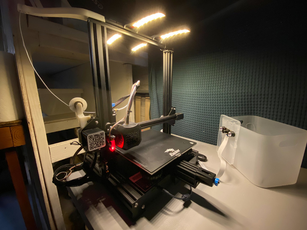
<p>Holds a couple dozen LED strips out above the printing bed.</p> <p>Suitable for printers that have an elevated vslot beam running across the middle of the bed, such as Ender 3, Ender 3 v2.</p> <p>Print it "fins down". Stick LED strip of your choosing to the other side. Solder wires to the ends of the strips, power the wires appropriately. I fed the wires down the vslot beams to steal 5V power from the ender board, but you may prefer to power it with a separate power supply, like a 5V or 12V adapter.</p> <p>I could fit 2 strips on each side, for a total of 24 LEDs, which is quite bright. It illuminates the bed and print well, and because there are so many lights, it reduces the effect of the shadow of the Z-beam on Ender 3 printers.</p> <p>There's nothing to stop you installing more than two of these, but I'm not quite that ferocious!</p> <p>If you are confident and are opinionated about how you want to print, build, and install this, you can go right ahead. Otherwise, read on for more detailed info about how to solder and add the LED strips etc.</p> <p>This is my first "thing", so let me know how it goes for you.</p> <h3>Post-Printing</h3> <p>First up, check that the printed case snaps on securely to the top beam of your printer. You may need to bend it firmly to open the "jaws" a little. Alternatively, you can remove the end cap of your v-slot and slide it along the beam.</p> <p>If that goes well, remove the case and get started with installing the lights.</p> <p>You'll need:</p> <ul> <li>LED strip (probably 24 units) with adhesive backing</li> <li>Appropriate power source for LEDs (e.g. power adapter - 1A usb charger is plenty for 5V strip)</li> <li>A "bare wire" connection to power source (e.g. USB cable to cut and strip)</li> <li>Optional: small power connectors (e.g. JST, barrel, xt30, etc.)</li> <li>Soldering iron, solder</li> <li>Flush cutters or craft/x-acto knife</li> <li>Wire strippers</li> <li>Light-weight insulated power cable (22AWG should be fat enough)</li> <li>Optional: thin brass or copper rod for bridging</li> <li>Optional: fine pliers for wire bending</li> </ul> <p>After printing you need to cut, solder, and install four LED strips: one pair on each side of the case. You'll also need a way to power your LEDs. You can provide power any way that makes sense (e.g. separate power adapter).</p> <p>First, measure how many LEDs you can fit on each side. With the strip I used, I could fit 2x6. Carefully cut these strips to length at the lines marked in the middle of terminal.</p> <p>Don't stick them down yet: soldering each pair together is easier when they're free.</p> <p>You'll need to electrically connect the positive and negative terminals of all the strips together so they can all be powered easily. You can do this however you want, but read on for my recommendation to make this quick and easy.</p> <p>First you'll need to solder the terminals of each pair together.</p> <p>If your strips have waterproofing material, cut this away on one side of each strip to expose the terminals.</p> <p>Orient the strips in opposite directions. That way you can bridge the "middle" terminal really easily with a short piece of brass rod (or uninsulated copper wire).</p> <p>If you have fine conductive rod available, soldering this across the terminals this is an easy and convenient way to connect the two strips together. (Otherwise, you can use insulated wire for this).</p> <p>This is a bit ugly – you can do better!</p> <p>I didn't have any fine pliers, so I just used flush cutters (very gently!) to bend the outer wire. If you're using insulated wire, just cut this to as short a length as you can easily solder.</p> <p>Now that you've got each strip bridged together in a pair, stick em down. Press down firmly for a few seconds to give the adhesive time to really grab hold.</p> <p>Now solder the pairs together using insulated wire. That way you can just apply power to one of the pairs, and they'll both light up.</p> <p>(If you used brass rod, this is especially easy because you won't easily knock the previous connections, especially for the outside.)</p> <p>This wiring will be almost completely hidden, so just do your best.</p> <p>Solder your power supply cable to one pair. If you are using power connectors available, you'll want to solder this on here. I am using a JST connector.</p> <p>Tip: power connectors are helpful because they allow you to configurations without soldering. For example, you can extend the distance to the power supply by building a new, longer cable. Or add additional lights and accessories just creating a splitter cable.</p> <p><strong>Now is a good time to test your connections. Here I'm using a bench power supply, but you can test with the supply you intend to use.</strong></p> <p>Now you can install your lights on your printer and hook up the power.</p> <p>In this picture I have made a basic power switch and a splitter cable to power two of these, for a total of 48 LEDs. You can use the center slot to route a small connector through to the top side if necessary.</p> <p>However, one case (24 lights) is perfectly bright. You can decide whether to upgrade to two (or more!) later.</p> <p>Optional: you may also secure the case through the two circular holes with V-slot nuts. You can search for "m3 v-slot nuts" to print these if you don't have any. Securing the light should be unnecessary, because the pressure fit is very secure. Any long term warping is unlikely to release the beam.</p> <p><strong>This photo is _entirely_ illuminated by these LEDs (the room lights are off).</strong></p> <p>And you're done.</p> <p>Enjoy your bright and convenient bed lighting!</p> Category: 3D Printer Accessories
With this file you will be able to print V-Slot "gantry" light (for Ender 3 v2) with your 3D printer. Click on the button and save the file on your computer to work, edit or customize your design. You can also find more 3D designs for printers on V-Slot "gantry" light (for Ender 3 v2).