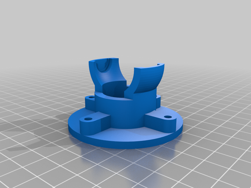
V2.0 Thrustmaster Warthog replacement gimbal
thingiverse
Please read! V2.0 of the gimbal is to address issues with calibration and strength in the gimbal, but is unfortunately a little more difficult to assemble. Of note is that the stock sensor mount is reused, but it has to be modified to fit. As this is a one way modification, I am trying to source a second base to get good pictures of the process for the build. Until then, I only have my prototype modification, which isn't pretty. Instructions to follow. My Thrustmaster Warthog base wore down and eventually had quite a bit of play in the gimbal. This set of STL files replaces the stock gimbal with one that uses Tamiya 1280 bearings, which are commonly available from hobby stores. Bearing dimensions Outer Diameter 12.0 mm Bore 8.0 mm Width 3.5 mm No other parts are required other than those in the joystick base. If desired, a 3D printable replacement sensor mount has kindly been made by Nopileus so you don't have to modify your stock one. https://www.prusaprinters.org/prints/44613-thrustmaster-warthog-joystick-sensor-holder-for-be Steps to build once all parts printed and stock gimbal disassembled. You will need to de-solder the ground line from the controller PCB. 1 - Install printed "stick holder" into stock grip bell. Rounded edge goes into the bell. Be careful to make sure that the wiring notch in the stick holder is on the wire side when installing to prevent damage to wires. Check that the wires are still free to move by unscrewing the connector on top, and moving the wires through the assembly. 2 - Install two bearings on the printed "inner gimbal" on the thicker edges. Of the four edges on the inner gimbal there are two that are thicker and two that are thinner. The thinner pair need to be thinner so we get a full 40 degrees of roll axis. 3 - Install the inner gimbal assembly into the stick holder, lining up the bearings with the slots in the stick holder that will accept them. This might be a tight fit and may need quite a bit of pressure to fully install. The inner gimbal should be able to move freely if it is installed correctly. 4 - Make sure stick holder is fully inserted, and as close to centered as possible. Due to the shape of the bell it is not possible for the stick holder to perfectly self seat in the bell, so try to make sure it looks even. This is best seen by looking for any differences in the depth the stick holder sits on both sides. Try and get these as even as possible. 5 - Install original grey sensor assembly into printed "outer gimbal". It might be a tight fit, but it will go in. 6 - In order to create clearance for the new mechanism, you will need to file down the original grey plastic of the sensor assembly. File it flush with the new outer gimbal assembly. 7 - Install the two remaining bearings on the remaining inner gimbal posts. 8 - Pass the grip wires through the inner void in the outer gimbal and out the bottom of the outer gimbal. 9 - Align the inner gimbal and outer gimbal so that the free bearings fit into the slots in the outer gimbal. Again, this may be a tight fit and require some pressure. 10 - Verify that grip wiring is still free to move. If not, try and figure out where it is stuck. You may need to disassemble the assembly to find where. 11 - Verify that the DIN socket's key is on the left side looking from the top, that the grip wiring is on the left side, and that the outer gimbal's base has the leg with two holes on the left side. 12 - Set assembly on to original metal base plate, with USB lead hole facing forwards. 13 - Invert assembly and screw in original forward and rear screws. 14 - Reassemble control logic board and re-solder earth lead, followed by screwing in remaining original screws over ground ring connectors. It is also possible to create a new earth lead by soldering a new wire on and attaching a ring connector. This makes it easier to remove components in future if necessary. 15 - Reassemble all other elements. Calibration will be required via the Thrustmaster Joystick Calibration tool (current version 1.13), which can be found on Reddit or the Eagle Dynamics forums. Don't forget to disable hardware dead zone in TARGET before calibrating in Windows.
With this file you will be able to print V2.0 Thrustmaster Warthog replacement gimbal with your 3D printer. Click on the button and save the file on your computer to work, edit or customize your design. You can also find more 3D designs for printers on V2.0 Thrustmaster Warthog replacement gimbal.
