Variable Compression Ratio Single Cylinder Engine
thingiverse
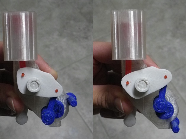
https://www.youtube.com/watch?v=JnUXYR0LcfU\nNissan isn't inventing a new idea with their variable compression ratio engine, but they're actually building this design so it's worth figuring out how it works. What better way than building a physical model yourself?\nOf course, this model and official video didn't exist yet so I couldn't build one myself.\nI watched the Engineering Explained video, but still found myself wondering "OK does that part spin or rock or what?" I thought I had seen an official gif, but there isn't one. I ended up just studying this video which thankfully got it right.\nPrint Settings\nPrinter Brand: MakerBot\nPrinter: MakerBot Replicator\nRafts: No\nSupports: Yes\nResolution: .2\nInfill: 100%\nNotes: There are 2 versions of the block, the standard one is really meant for transparent filaments, the "windows" version has holes in the sides of the cylinder so you can watch the piston travel even through opaque plastic.\nThe angle of the angled bit is right on 45 degrees, so it'll probably come out a bit droopy.\nPrint one of each part except for the end ring (you'll need two).\n100% infill is really only necessary for the spinning/cranking bits, you can get away with less on the block, piston, rockers, and maybe even the links.\nPost-Printing\nAssembly\nSanding! So much sanding.\nI've finally picked up a Dremel-type rotary tool, but even then sanding the cylinder bore by hand was still extremely tedious.\nYou'll need maybe an inch of 1.75mm filament to make the piston wrist pin and pins for the links/rocker.\nPretty much everything should be friction fit, I didn't use any glue, but there are a few parts that I melted together with a 3D printing pen tip.\nI started by sanding the cylinder bore and the piston until they were sliding well. Run a drill bit through the holes in the block. Before sanding on the crank and control pins, I'd recommend drilling out the holes in the crank/control shaft parts so you can fit the pins in, giving you more to hold on to for sanding. Wait to drill out the holes in the handles/end rings/rockers/spacer, as the holes you end up needing may be a bit smaller than the pins are fresh out of the printer. The end rings can be a tight fit, but pretty much everything else needs to be drilled/sanded enough to rotate smoothly. When you're ready to push the control handle onto the shaft, line the shaft up with one of the marks on the block, and then line up the handle with the opposite endstop. Lining up the crank handle and shaft is less important, but remember the spacer that keeps the handles from running into each other. Drill out the holes in the piston and the smaller holes in the rockers and links to fit 1.75mm filament. Assemble the piston and upper link and slide them into the cylinder bore. Slide the lower link onto the control shaft. Make sure you have the rockers oriented correctly, and then slide the back one onto the crank, line the holes up with the ends of the links, and slide the other rocker on and the pins through the holes. You will probably want to permanently fix those pins into at least one of the rockers. Check that the engine cranks smoothly, and then pop those end rings on.
With this file you will be able to print Variable Compression Ratio Single Cylinder Engine with your 3D printer. Click on the button and save the file on your computer to work, edit or customize your design. You can also find more 3D designs for printers on Variable Compression Ratio Single Cylinder Engine.