Variable Power supply Enclosure
thingiverse
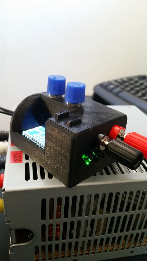
Do you need a variable bench top power supply with the looks and feel of a super expensive high quality one? Then look somewhere else... However, if you've seen those cheap DC to DC buck/boost converters on Aliexpress then this enclosure is sure to tickle your fancy, whet your appetite, moan on your phone, slam your ham, fever your beaver, etc. **STEP 1 - The Gathering (not the 2002 film)** To complete this project you'll need the following bits and pieces- 1. DC to DC Buck Boost Converter 0.5-30V 4A Output https://www.aliexpress.com/item/32900690310.html?spm=a2g0s.9042311.0.0.58e64c4dP28ZFM 2. 100k Potentiometer x 2 https://www.jaycar.com.au/100k-ohm-linear-b-single-gang-9mm-potentiometer/p/RP8518 3. Red Panel mounted Binding Posts for 4mm Banana Plugs https://www.jaycar.com.au/red-deluxe-binding-post/p/PT0453 4. Black Panel mounted Binding Posts for 4mm Banana Plugs https://www.jaycar.com.au/black-deluxe-binding-post/p/PT0454 5. 4 x 6mm M3 screws https://www.jaycar.com.au/6mm-x-3mm-steel-screws-pk-200/p/HP0401 6. Soldering Iron + Wires + Heatshrink + skillz **STEP 2 - The main event (3D printing)** So now that you've raided your local Jaycar and ordered the correct power supply from Aliexpress, you'll need to print the following parts in the following quantities in the following orientations - *1. Housing V3 x 1* Print this on its head (so that space where the power supply mounts and the M3 threaded holes are facing up). I designed it to be printed this way, any other orientation would mean unnecessary supports and wasted filament. *2. Knob V1 x 2* Print this upside down (with the hole for the potentiometer shaft facing up) *3. SWAV2 x 2* Print this upside down (with the hole for the secondary shaft facing up) *4. SWBV3 x 2* Print this with the thinner piece of the shaft pointing up I had no issues printing all these pieces in these orientations, except for when my nozzle clogged and I had to wait a week for a new one T_T **STEP 3 - The Nitty-Gritty (Modifying and Mounting the Power Supply)** 1. After you've printed all those parts and received your power supply in the mail, get two thick pieces of wire approximately 10cm long (preferably red and black) and wire them to the INPUT side of the power supply (red for positive and black for negative) 2. De-solder and remove the two blue trimpots that are used for varying the current and voltage. 3. Prepare some thinner wires approximately 5cm long, to connect both 100k potentiometer (pot) to the board in place of the blue trimpots. This is where the skill comes in... ***TIP*** strip both ends of the wires before starting to solder anything, as it can get really difficult to strip wires that short. ALSO I would start soldering wires to the pots first, and then solder to the power supply, as it can be hard to line up the wires with the pots when you don't have more than two hands. DO NOT mount the potentiometers into the housing just yet! 4. Solder two thicker gauge wires to the red and black binding posts... THEN mount them into the housing... AND THEN solder the other ends to the power supply circuit board. 5. Assemble SWAV2 and SWBV2 together and slide them into the holes in the housing 6. Now you can mount the potentiometers in place (if we tried to do this earlier everything gets a bit hard) ensuring that the protruding notch of each potentiometer lines up with the indentation on the housing. Then secure them down with the washer/nut. 7. Use the four M3 screws to now fasten the housing to the power supply, but do not tighten too much as the plastic threads can easily strip. Watch the screw as you tighten it and stop when it is flush against the circuit board and the board no longer has a lot of play. 8. Finally rotate the potentiometer shafts completely counter clockwise, then push the two knobs onto the shafts, with the indicators pointing to the 7 o'clock position **STEP 4 - Time... to... FRY** Hook up the fat red and black wires you connected to the input to either a 12V battery or a mains DC power supply (anything over 5V should work) and the power supply should switch on. Pressing either of the two buttons toggles the voltage displayed (input OR output voltage) or switches the output voltage ON or OFF. Rotating either of the potentiometers varies the voltage (in constant voltage mode), or current (in constant current mode). Now crank up the power and lick it..
With this file you will be able to print Variable Power supply Enclosure with your 3D printer. Click on the button and save the file on your computer to work, edit or customize your design. You can also find more 3D designs for printers on Variable Power supply Enclosure.