Vertical Wind turbine and 3Phase alternator 9 Coils / 12 magnets
thingiverse
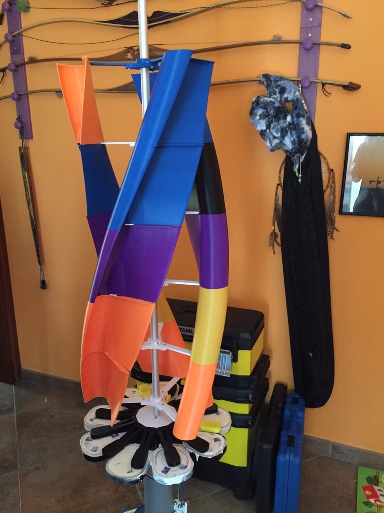
This is my first alternator design, I'm not an engineer, if you see that something is wrong or have any suggestion or comment will be appreciated. I've started to think about a 3d printable alternator looking at the Lenz2 Helical Turbine XL, that design is beautiful and effective but is missing of a home makeable generator. For two weeks I've read all the document I found about generator/alternator/AC and DC current/Rectifier/Charging circuits. This lead me to my design, a 24 volt 3-phase alternator. 24 volt mean more volt in low speed but a lot in high-speed, almost for sure I'll need to made a MPPT charging circuit. 3-phase seem to be more efficient than a single one but you have to made/buy a 3-phase rectifier that is more expensive. How many coils and how many windings was the result of a day playing with the Faraday's Law. Follow the schematics (by Jimmy of Eirbyte) for the star configuration, if you want you can try also a delta configuration, bot will give the same amount of Watts but the star has more Volts and less Ampere and the Delta will have less Volts but more Ampere. Because I choose to work with MPPT hardware to charge my battery I prefer more Volts. I'll update this thing constantly during the build process, now we are at revision 0.31 ////// NEW DESIGN ////// After a field test on the alternator the result was not satisfying and I choose to redesign the whole stator and rotor to fit bigger coils 5 times more copper than the previous version with smaller wire. At this point the coils are a bigger then before, for this reason the new design has the coils horizontal. The new stator design will have 9 coils with 350 turns of 0.6mm wire (old was 50 turns with 1.2mm wire) half of the magnets but twice the size. (40x20x10) One of the problems of the old design is the difficulty to cast the coils, in the new design the stator arm is also the container for the epoxy resin in this way will be easy to cast the coil when all is working correctly. After a single coil test seem that the output is around 5V at 2 turns per second, next test will be with the 3 coils connected together. The next test is 3 coils in series connected with the rectifier and the rectifier is connected to an output capacitor. Without load the capacitor charge up to around 24,5VDC, with a small load 0.5A the power output is stable at 12VDC Now is time to cast the coils while printing the blades. To cast the coil I used a dielectric resin designed for this work, is less expensive then standard epoxy or other type of cast resin. After casting the first phase, waiting for the wire to be delivered I've started printing the blades, the blade design come from the lenz2 wind turbine, I have remixed some parts to adapt it to my needs. I suggest using ABS for the parts, PLA melts under direct sunlight in summer (just discovered this today during a field test!) and is more easy to machine if needed. I've finished to cast all the coils, the generator output around 12V (depend on the load) in a moderate wind dey. I still waiting for a good windy day to do an appropiate test. Now I'm printing more blades, the minimum to make the rotor move is around 4/5 layers. Actually my plan is to test a 6 layers configuration in a moderate wind to see how many Amps I can draw and on this result decide if an additional layer is needed. Testing with the oscilloscope the curve highlighted that probably my 3'phase rectifier is a bit overrated, the diodes cut to many volts, I want to try some 6A diodes that will cut only 950mv instead of actual diodes that cut around 2v. I think that in this way I will produce less Amps but a more stable rate. ////// OLD DESIGN Pre rev 0.9 ////// The generator is a low rpm designed for a vertical wind turbine. it may output alternate current (AC) around 24V at 120 RPM. This current must pass trough a 3 phase rectifier to have a suitable DC current to charge batteries. There two type of rectifiers, half wave and full wave, for efficiency I suggest to buy/build a full wave rectifier. (in the gallery an image of 3 phase and as they come out from the alternator and the same wave rectified) (Wave image from Wikimedia by Krishnavedala) (Rectifier image from Wikimedia by Sonarpulse) My alternator is made of 18 Coils and 24 Magnets with a Magnets to Coils ratio of 4:1 Inside the gallery there the calculation for coils windings to get 12 or 24 volts. (I can't be more specific until the first test on the field!) This design is inspired to the "Lenz2 Helical Turbine XL", I plan to use the wind blades from this design. The stator is in two pieces, the core and the coils holder. Print the stator and put your coil in the coil holder, fix it with epoxy and glue the holder to the stator. The stator will snap in a 90mm tube and will hold a 47mm conic bearing to hold the rotor and the main shaft. Inside the 90mm tube will be an internal part to hold another 47mm bearing, this two will hold the rotor and the main shaft, The rotor is in 8 pieces, the main part to print six times and the plates, the part is made to hold 24 40x10x10 N45 magnets. Handle with care this magnet, they can be dangerous, use eye protection and gloves. The internal bearing holder is placed inside the 90mm tube and holds the main shaft with a 47mm bearing To keep the 90mm tube vertical is provided an outer ring to hold 4x20mm tubes at 45deg. To keep the main shaft in place two rings are provided, one goes on top of the conic bearing inside the stator and one goes at the end of the tube. I suggest using ABS for the parts, PLA melts under direct sunlight in summer and is more easy to machine if needed. Changelogs: Rev 0.31 27/7/15 - Added build instructions Rev 0.30 27/7/15 - Updated documentation Rev 0.29 25/7/15 - Updated documentation Rev 0.28 24/7/15 - After the field test i finally decided to cast the rotor with resin. (see picture) Rev 0.27 22/7/15 - Updated blade attach arm to better fit Rev 0.26 19/7/15 - Remade Blade attach system to be more strong Rev 0.25 19/7/15 - Added blade STL Rev 0.24 19/7/15 - Added parts to holding blades Rev 0.23 18/7/15 - Tested coil casting on single phase Rev 0.22 18/7/15 - Tested 3 coils and power rectifier Rev 0.21 18/7/15 - First single coil test give good results, addedd gallery pictures Rev 0.20 18/7/15 - Updated gallery to show up assembly progress Rev 0.19 15/7/15 - Updated rotor core to reduce gap between rotor and stator, this will improve performance Rev 0.18 13/7/15 - Starting field test with 350 turns coils Rev 0.17 11/7/15 - Modified rotor arm, was a bit weak on the joints with the magnets. Rev 0.16 10/7/15 - After a field test I choose to decrease the wire size and increase the turns, during the test the new parts worked very well, all spin freely and is very easy to tune the distance between magnets and coils Rev 0.15 9/7/15 - Updated rotor arm to better handle overhangs Rev 0.14 9/7/15 - Updated stator arm to better fit coil Rev 0.13 9/7/15 - Updated rotor core and stator arm to better prints overhangs Rev 0.12 6/7/15 - Updated rotor core and rotor Arm Rev 0.11 5/7/15 - Added 90mm tube cap and fixed some tolerance issues on the Stator Core and the Rotor Core Rev 0.10 5/7/15 - After a first test the voltage is way too low, around 6-7v, and I choose to drastically change the design. Rev 0.9 2/7/15 - Added coil connection schematics and descriptions Rev 0.8 2/7/15 - Added top plate, gallery pictures, added partial assembly instructions Rev 0.7 2/7/15 - Added holding rings and gallery pictures. Updated documentation. Rev 0.6 2/7/15 - Added rectifier schematics and 3 phase schematic Rev 0.5 1/7/15 - Modified the outer ring and legs to fit better 20mm tube (tat are not exactly 20mm). I choose to make the holes wider and glue the legs with epoxy. Rev 0.4 1/7/15 - Modified the winder tool to be a bit taller. Rev 0.3 30/6/15 - Modified the inner ring to better fit inside the 90mm tube (that is not really 90mm but a bit smaller) Rev 0.2 30/6/15 - Modified the coil holders to be adjustable and reduce the gap between coil and magnet Rev 0.1 30/6/15 - Modified the stator to fit inside my printer.. :) was 2 mm too large. Rev 0.0 30/6/15 - Design published Additonal 3d printing and drone racing "stuff" on my youtube channel (iZeeFPV): https://www.youtube.com/channel/UCX7UjdoPqErjrR2nYaxkqCw
With this file you will be able to print Vertical Wind turbine and 3Phase alternator 9 Coils / 12 magnets with your 3D printer. Click on the button and save the file on your computer to work, edit or customize your design. You can also find more 3D designs for printers on Vertical Wind turbine and 3Phase alternator 9 Coils / 12 magnets.