Viper Throttle
thingiverse
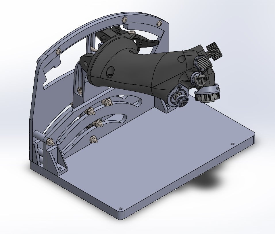
So! This is a little project I started a good while ago to a) get a viper throttle grip with working potentiometers, switches, etc. that can be wired up with an arduino and freejoy/mmjoy and b) mimic the long travel of a real F-16 throttle without needing an 8 inch long lever arm. The first goal is just about complete. The latter is still WIP. The complete assembly is about 7.5" tall, or about 3.5" shorter than a simple pivot would have to be. Still pretty big if you're putting it on your desk, but definitely a more usable size. I may try to draw up an even shorter version when I have some time. The main thing I'm not 100% happy with yet is the main throttle sliding action. While my current prototype proves the concept, I don't have a great way to adjust tension on the throttle arm. There is currently some sticktion, and the throttle arm can jam if it's twisted as you push or pull it, but I think increasing the stiffness of the side plates would fix that. Anyhow, this is WIP. I'm uploading a SolidWorks 2020 PacknGo as well as a step file and stl's of the printed parts. If you have suggestions or comments please shoot me a message either here or on the HOTAS Discord. All parts were tested in PLA either on my direct drive Ender 3 or on Prusa i3 Mk3s printers except for the base and side plates of the main base assembly. I designed with #8 bolts in mind, often threaded directly into the printed parts. M4 hardware should be directly interchangeable in most cases. Notes on the Project: For the grip, I started with the excellent model from the Hempstick Project. I had to do some editing to several parts in order to make the switches and potentiometers I was working with fit and function inside. I drew up the slide switch housings to take MTS-103 on-off-on (dogfight switch) or MTS-123 (on)-off-on (speed brake switch) switches which I purchased off Aliexpress. The switches just screw into the base of the housing and the cap just sits in its channel and slides back and forth. The hole in the base of the cap should be sized just correctly, though with a few of the switches I got it was a little small. The speedbrake switch is installed by inserting and twisting the assembled switch clockwise. It may be a tight fit. The antennae elevation switch was designed to take a potentiometer with center detent. A non-detent pot will work as well (and will probably be much easier to find), but there won't be any feedback for center position. The pot is a little difficult to install, but it will fit inside. I got mine off digikey (https://www.digikey.com/en/products/detail/bourns-inc/PDB181-K220K-103B/3780701 or https://www.digikey.com/en/products/detail/tt-electronics-bi/P164K101PNN20B103/12162423) The manual range knob I just used a normal rotary potentiometer. Ideally this would be a potentiometer with a built in push button as well; however, I was unable to find one at a reasonable price so I added a provision where you can just add a tact switch behind the potentiometer. This make the pot a little wobbly, but it's totally optional. The comms switch is taken from my 4/5 way tact swtich design (https://www.thingiverse.com/thing:4543158). However, I did modify the base file, adding two nubs so that no screws are required to mount it to the throttle. Everything else is the same. The comms switch cap is one I made up based on pictures and guesses. I couldn't find any good reference material for modelling an accurate one. The Radar Cursor is a simple PS3 thumbstick which I purchased off Aiexpress. The thumbstick snaps into a housing which then inserts into the throttle body. The hat for the thumbstick is somewhat guesswork as well, but better than the comms switch. The throttle grip itself is printed in four pieces. There are the two parts of the grip itself, and then also the front and rear arms which attach the grip to the lever arm. I split those off so the bottom grip could be printed on its side. They should pressfit in, though they may be a bit tight. Once everything is printed they can be glued in. The grip is held onto the lever arm (file: Arm 6.0) with a single bolt; I used a 2.5" long 1/4"-20 bolt but an M6 ought to work as well. The large flat plates for the throttle base and side panels were laser cut out of 1/2" and 1/4" acrylic. I intend to edit the design to make the side panels 1/2" acrylic since I believe the design would benefit from the increased stiffness. This will necessitate a redesign of the angle brackets and the bottom base as well. On the base there are a few pocketed areas in the corners. I added these so that I could add nerf dart heads to the base (specifically Worker Gen 3's which have a nice rubbery tip. Don't even bother trying official nerf darts) to prevent the assembly from sliding around on the desk. The Worker dart heads work very well. When lasercutting the plates, I used a deep engraving setting in the lasercutter to create countersinks and similar things. These plates could also be made with a CNC router, or just 3D printed. I will include stl's of them in addition to dxf's and the step/solidworks files. The plates are held together with 3D printed angle brackets. These are something I drew up super quickly when I was prototyping because I wanted to test the profiles and all. Unfortunately that means they're annoyingly specific to their location as I worked to get all the bolts where they need to be and not interfering with each other lol. There are four brackets, and the stl's are all labelled with their location (LR (Left Rear), RR (Right Rear), LF (Left Front), RF (Right Front)). These will be changed for sure when the plates are edited. The bearings used on the throttle arm are 685zz bearings (11mm OD, 5mm ID, 5mm W). I printed thin shims in order to fit these to #8 bolts (again, M4 hardware should be very close). I may edit this to take #10/M5 hardware in future. The throttle arm has an additional bolt that should be used to tension the bearings and eliminate slop where the arm interfaces with the plates. The outer side plate contains a 3D printed track which contains the idle and afterburner detent. This track conforms as closely I could manage to the real F-16's system; I believe it is very accurate. I drew up (but did not test print!) a cover for the base which would allow you to mount additional buttons/switches to the base, as well as have plenty of room for a microcontroller and such. There is a channel in the Arm and an extended cut in one of the bearing slots on the inner side plate for routing wires from the throttle body and into the base area. A potentiometer measures the throttle arm position by use of a long arm with a slot in the end. This does not give a precise 1:1 measurement of throttle position, but the non-linearity is most concentrated in the idle cutoff section of the travel and at the end of afterburner. I don't think the issue will be particularly noticeable in day to day usage. The pinkie switch is in good shape except for lacking a spring to spring it back. Ideally I'll work something out with a torsion spring soon. I also don't currently have a spring tensioning the main throttle as it hangs on the arm; will probably try to put a torsion spring on their as well. So yeah, that's a basic overview of everything I can think of at the moment regarding all this. I was wanting to fix more of the issues before publishing but it's already been like a month beyond when I was hoping to publish initially. I'll continue working on this in my spare time but I wanted to get at least the grip into the open! Once again, feel free to message me here or on the HOTAS Discord. Also feel free to drop a tip if you feel like anything I've done here deserves it (but no pressure lol). I'll post updates here as they come and mention them in the HOTAS Discord as well! Happy printing/flying!
With this file you will be able to print Viper Throttle with your 3D printer. Click on the button and save the file on your computer to work, edit or customize your design. You can also find more 3D designs for printers on Viper Throttle.