Virpil CM2 Throttle Fingertip Detents
thingiverse
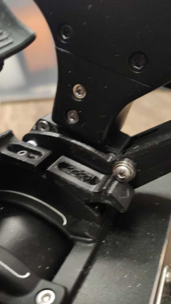
This is meant to be an upgrade kit for you Virpil CM2 Throttle to have a similar detent system like the new CM3 one. ATTENTION this is not an easy update, you need some mechanical skills, a Ø3mm drill set, M3 thread cutters, a Dremel with cutting disc and eye protection using it!, a vice etc. And a good amount of patience :-) Be aware you might lose your Virpil warranty aplying this mod! The STL files resemble the left side of the engine lever, for the right one, they have to be mirrored in your favorite slicer, except for the finger tip lever (Griff neu R) I suggest, you start with the left throttle and check how it works, then print/assemble the right side. For one side you will need: 2x cylinder head inbus screw ISO 4762 M3x30 2x cylinder head inbus screw ISO 4762 M3x15 3x counter sunk inbus screw ISO 10642 M3x20 (cut them to 19mm) 2x pan head inbus screw ISO 7380 M3x16 1x pan head inbus screw ISO 7380 M3x14 ~4x pan head inbus screw ISO 7380 M3x12 (for the detents) 3x Ball bearing MR 83 ZZ 3x8x3 2x self locking nut ISO 10511 M3 8x nut ISO 4032 M3 2x washer ISO 8738 M3 (2x worm screw ISO4024 Mx6) Start by printing "Klemme L" + "Klemme R" and "Schenkel L" + "Schenkel R" and "Spacer" Flat side on print surface, support enabled high infill and print quality I used 80% infill and 0.1mm layer. You need to bend your own springs, this can be done with in a simple mount with two M3 threaded holes in it and two screws. Use 0.7mm or better 0.8mm spring steel wire, I got mine f.e. from ebay f.e. https://www.ebay.de/itm/1m-Federstahl-Hutdraht-Draht-Spring-Wire-0-8mm/371993998780?hash=item569c91f5bc:g:PUUAAMXQn11RcnXM The spring has to get 2 full windings plus an additional 90° The left side of the throttle needs a right hand winded spring. This spring is shown on the right side of feder.jpg Fit the two MR33 bearings in the Ø3x8 hole of the "KLEMME L/R" parts, fit 3x M3 nuts too. Eventually it is a good idea to take an Ø3 drill bit and drill all the holes of the KLEMME part for an easy fit of the M3 screws...(Don't do this on the SPACER part!) Take an M3 thred cutter and drill the M3 thread for the two additional worm screws. This is optional, the one in the back of KLEMME is for additional pressure to keep the part in place, the other one is for fine tuning / synchronizing the ball bearing position, which can also be done by adjusting the height of the KLEMME parts. Clip the two "Klemme" parts around your left throttle base, insert the spring and fix it with the countersunk screw Mx20 (wich you have cut down to 19mm with your Dremel!) Take the "SCHENKEL R" part, apply a 'flat' M3 nut and the pan head M3x16 screw together with a ball bearing. When the screw barly comes out of the "SCHENKEL" part, insert it into the "SPACER" part and tighten the screw, so that the bearing still can turn freely. Be carfefull not to overtighten! Take the long M3x30 screw, stick it through "SCHENKEL R" assembly and apply one of the M3 washers. The punshed washers have a concave side, which should point towards the SCHENKEL part. Stick this through the ball bearings, apply another washer (concave side pointing outwards) and the "SCHENKEL L" part followed by thje M3 lock nut. In this process you have to insert the left arm of the spring into the openeing in the spacer, this might be a bit tricky... Don't tigthen too much, it should have a fair amount ~0.2-0.5mm play. Aligh the "SCHENKEL L" part, so you can mount the second M3x30 screw trhrough the top hole of the SCHENKEL parts. Secure this with a self locking nut. Screw an M3x14 screw through the opposite side of the bearing mount. Be carfefull not to overtighten! Print "GRIFF neu L" with support, fine settigs, align the left flat surface to your print bed. I used to print this part alone, otherwise it would like to jump into freedom ;-) Use the M3x14 and another M3 flat nut to secure the "GRIFF neu L" part. Print the "KULISSE" part with support and use your best quality layer height, I did it with 0.1mm Put 3 flat M3 nuts inside the "KULISSE" part. Unscrew the two center screws on the CM2 and fit the "KULISSE" part with two cylinder head screws M3x15 Repeat the whole process mirrored for the right engine throttle. Adjust the heigt of the KLEMME (the countersunk screws are accessible in mounted state!), so that both bearings are synchronized. Print the detents with support, lying on their side (this will produce the smothest surface quality for the contact faces of the ball bearing!) Fix your preferred detents with M3x12 screws. The center hole in the "KULISSE" part is actually unused. Some words on the cosmo detent, I tried to hit the 75% spot for elite dangerous. For super cruise flying you would normally use a predefined button to enable 75% throttle. In combat, the 'blue sweet range' on the screen throttle will vary from ship to ship, so keep in mind, the detent is just a reference, rather than a precise spot. Changes: 08.04.2021 Updated the Afterburner detent to AfterburnerDetentV2 and added STEP, STL and a jpg Corrected the typo in the ball bearing designation
With this file you will be able to print Virpil CM2 Throttle Fingertip Detents with your 3D printer. Click on the button and save the file on your computer to work, edit or customize your design. You can also find more 3D designs for printers on Virpil CM2 Throttle Fingertip Detents.