Walking Dinosaur Robot
prusaprinters
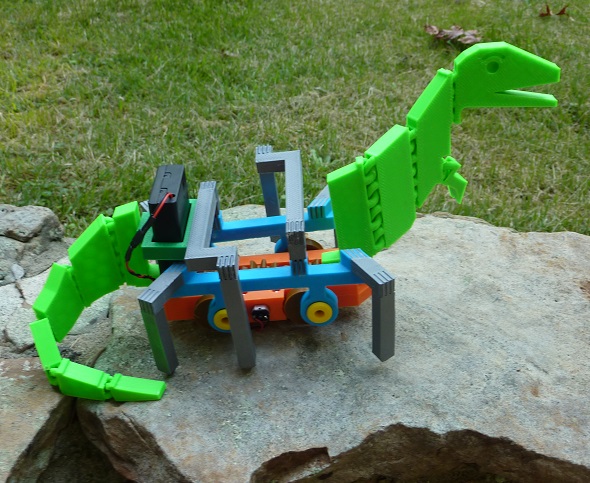
<p>The robot has a ponderous gait.</p><p> </p><figure class="image"><img src="https://media.printables.com/media/prints/278556/rich_content/44db03ac-2683-4a0f-8474-41db00c9dc07/p1070226mov_8fps_400_pixels.gif#%7B%22uuid%22%3A%2274a515e1-c583-42d0-b908-08d9e3c7be9d%22%2C%22w%22%3A400%2C%22h%22%3A300%7D"></figure><p> </p><p> </p><p><strong>Printing</strong></p><p>Generally I use a 0.25mm layer height and put about 1mm of plastic on the outside surfaces as a shell. Since my printer has a 0.5mm nozzle I use 2 vertical shells and 4 horizontal top and bottom layers. I set a honeycomb fill pattern with a 15% honeycomb fill density. Support isn’t needed when printing the parts for the walking dinosaur robot but the screw holes in the frame may need a bit of clean-up from filament stringers.</p><p>The dinosaur tail needs to be rotated about 30 degrees to print on a 200mm print bed. Slowing the print speed helps in keeping the coupling links from curling up while printing the head and tail.</p><p><strong>Extra Components needed for Construction</strong></p><p>You’ll need two axels (58mm long) cut from 1/4” dowel (try 6mm as a substitute and try to get a hardwood like oak). Acquire an assortment of M3x10mm cap screws and M3 nuts (you’ll need 8 sets plus any extra you plan on dropping). A hex driver that fits the screws will be handy. I use super glue (cyanoacrylate - CA) to hold ABS parts together. You will also need 2 M4 nuts for clamping the drive gear. The “bearing” support for the end of the motor shaft is a #6 washer (they come in a package so you’ll have extras).</p><p>The driving force for the robot comes from a miniature 30RPM gear motor (with a M4 threaded shaft). The M4 nuts clamp the drive gear in place. These motors can be found on eBay, Amazon or <a href="https://www.aliexpress.com/item/2251832735039939.html?spm=a2g0o.productlist.0.0.482f385311jVEs&algo_pvid=6ca5fe56-0a30-47a3-941b-8c9d0d3a612c&aem_p4p_detail=2022090707180814772115715161300000549566&algo_exp_id=6ca5fe56-0a30-47a3-941b-8c9d0d3a612c-4&pdp_ext_f=%7B%22sku_id%22%3A%2266049126665%22%7D&pdp_npi=2%40dis%21USD%213.81%213.62%21%21%21%21%21%402103255a16625602887652883e246e%2166049126665%21sea&curPageLogUid=naP84tzDTVPH&ad_pvid=2022090707180814772115715161300000549566_1">AliExpress</a>. If you purchase one from China the delivery time can be up to a month. Obtaining one from a <a href="https://www.neweggbusiness.com/Product/Product.aspx?item=9siv0kk9ca1455&bri=9b-30p-0066-00gj3">local supplier</a> will cost more but provide faster delivery. I found that the 3V motors will operate well at 6V with a lot of torque. You’ll need a <a href="https://www.ledsupply.com/accessories/aa-battery-holder-switch-leads">battery pack</a> with a switch. You may want to purchase one for 2-AA batteries and one for 3-AA batteries. The battery pack with 3-AA batteries provides 4.5 Volts and will operate the motor a bit faster with more torque.</p><p><strong>Assembly</strong></p><p>There are 4 nut traps on the frame top and one each in the 4 “leg drive discs”. Start a M3 nut onto the end of an M3x10 mm screw. Using the screw as a handle, push the nut into the nut traps (note: it may be necessary to drive, hammer, or pound them into place. Alternately, you can put a longer screw up through the hole from the other side and start the M3 nut. Then using the hex driver you can pull the nut into the nut trap making sure the points are lined up.</p><p>The shaft on the motor extends beyond the robot frame. You can cut it to length with a hacksaw or grinder if desired. Screw the M4 nuts onto the shaft first to clean up the threads when you back them off after the cut.</p><p>Temporarily screw the two halves of the frame together. This also seats the nuts in the nut traps. Then clean out the axel holes with a drill slightly larger than the axle material (17/64” for a ¼” dowel). Make sure the axles can rotate smoothly.</p><p>For a neater construction the motor wires could be twisted together before soldering. Cut two wires to length (about a foot, you can cut the twisted pair to length after twisting) and chuck the ends into a drill clamping the jaws tight to hold each wire. Put the drill in “reverse” at the lowest speed. Pinch the wires at the drill chuck with your fingers and start the drill, running your fingers up the wires as they twist.</p><p>Solder the wires onto the motor for later connection to the battery box that will be on the end of the robot frame. Note there is a “+” terminal on the motor. Remember which wire was connected there. While the motor will operate in either direction the manufacturer may have thought this was the optimum direction (I really don’t know).</p><p>Glue a gear onto the center of each axle. If it’s tight, it can be driven on without glue. If it’s loose from your printer set-up or you drilled a larger hole, glue will be needed for assembly. Put the drive gear onto the motor shaft with an M4 nut on each side. Adjust the nuts so the gear is in the center of the frame opening when the motor is in place. Don’t tighten the nuts just yet. </p><p>Re-assemble the frame with the axles and motor in place. Don’t forget the #6 washer in the slot supporting the motor shaft. Attach the leg_drive_disks to the leg_support_frame using an M3x10mm screw through the spindles. (Note: See the photo for orientations.) Then glue the leg_drive_disks onto the end of the axles with enough clearance that the shafts are free to turn. Note: the leg drive disk orientation is 180 degrees out of phase on opposite ends of the axle (i.e. If one side is up the other side is down), and the nut traps in the leg_drive_disk will be on the side toward the frame. Turn the main drive gear to make sure that everything rotates without binding. Then tighten the M4 clamp nuts on the motor shaft (if you don’t have wrenches thin enough you can dissemble the frame temporarily).</p><p>Glue the (corner_legs) angled leg extensions into the angled splines on the corners of the frame. Glue the (leg_cross_over) short vertical extensions to the splines toward the center, then glue on the center cross pieces keeping everything reasonably square. Finally glue the vertical legs in place. </p><p>Temporarily connect the battery pack to see which way the robot moves. The dinosaur head snaps onto the front and the tail snaps onto the rear. Drop the battery pack into the holder and solder/connect the wires. </p><p><strong>Adjusting the Robot’s Gait</strong></p><p>The dinosaur head should swing back and forth as it walks. The joint elements between the sections are set at a 45 degree angle for easier printing. This gives the sections a tendency to curve to the right because of gravity. To counter act this effect the clamp for the head is at a shallow angle from vertical that tilts to the left. There are two head files, one is square and one is tilted. Try the angled one first.</p><p>The battery packs with 2 or 3 AA batteries allow a walking speed adjustment. If you want a more ponderous speed a 15rpm motor could be used. If you want to try this option do an internet search for”3V 15rpm gear motor with M4 shaft” or order one from the Chinese supplier.</p><p>Finally, the “robot_frame” platter contains a copy of the head/tail clip in case someone might wish to attach alternate heads or tails to the robot.</p><p> </p><p>Maybe the Cleveland train station was taken over by dinosaurs?</p><p> </p><figure class="image"><img src="https://media.printables.com/media/prints/278556/rich_content/6857f4e4-e1b7-42db-822c-37aa16e12317/p1070236mov_7fps_400_pixels.gif#%7B%22uuid%22%3A%220dbc73f3-e668-4ff5-9296-1e92b81cc61a%22%2C%22w%22%3A400%2C%22h%22%3A300%7D"></figure><p> </p><p> </p><p> </p><p> </p>
With this file you will be able to print Walking Dinosaur Robot with your 3D printer. Click on the button and save the file on your computer to work, edit or customize your design. You can also find more 3D designs for printers on Walking Dinosaur Robot.