Walking Toy Robot
thingiverse
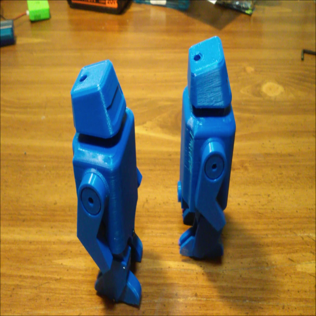
This is another walking robot toy design. It's a little different from the pin walkers I've posted before. It has legs that bend at the knees to give a more realistic walking motion. The ideal behind it was to turn the pin walker mechanism inside out. On the other pin walkers I've built the pin is inside the stationary leg. It moves in an elliptical motion to drive the toy forward. In this design, the pin is stationary and the leg moves in the elliptical motion. The outside facade of the leg is made of the upper_leg that pivots at the top and the lower_leg that connects to the foot of the leg. The two pieces are connected at the knee. The leg moving up and down causes the knee to bend. This is purely astetic. I'm sure the mechanism is nothing new. It also has swinging arms for a little added animation. There are pins on the top_leg parts that mate to slots in the arms so they swing opposite the legs. The toy has a minimalist look. It can be printed and built in a day. The hardest part of the assembly is the wiring. The pivots are made from T-pins I bought at Wal_Mart. They have a 1 mm diameter. The motor is a commonly available 6V 100 rpm N20 gearmotor powered by a 150 mah lipo. The batteries were purcased from Banggood and came with a charger and the small jumper cables. You need to use one of the cables to hook the battery to the motor through the switch. The switch is from a tea light. The battery is mounted with double sided tape. The switch is under the back of the head. When you mount the switch with hot glue, it should be approximately 1mm proud of the frame. It's hard to get to, so I use a screwdirver to turn it on and off. The top of the head is held onto the bottom of the head with a 2mm X 8mm self tapping screw. You can access the connector for the battery to recharge it by removing the top. I also use a 2 mm X 8mm screw to mount the main body to the frame since I didn't have enough room for a 3d printed screw. Th last 2mm screw is used to hold the clamp part to the frame. The clamp holds the shaft, crank, gear assembly in place. Refer to the video for details. https://youtu.be/Uk0YLWfCYR0 Parts: 6V 100 rpm N20 gearmotor 1/8 inch or 3mm dia X 38 mm long rod. I used 1/8 inch brass brazing rod. 3 ea 2mm X 8mm self tapping screw 150 mah lipo and connector https://www.banggood.com/5PCS-Eachine-E010-3_7V-150mAh-Battery-RC-Quadcopter-Spares-Parts-p-1081736.html?rmmds=myorder&cur_warehouse=CN switch from a tea light 1mm diameter T-pins small flexible wire and heat shrink tubing super glue and hot glue Build notes: Make sure to remove all burrs, bumps and anything else that might interfere with free movement. I use a small rat tailed file for inside holes and gear teeth, but a hobby knife would work. A sheet of 200 grit sandpaper on a flat surface works for flat parts. A nail file board also works well. There are several 3d printed threaded parts. The internal threads should be cleaned out with a 6mm X 1mm tap. If you don't have a tap you may be able to use a 6mm bolt with a groove dremeled into it. I haven't had to use a die to clean up the external threads. Run a tap through the threaded holes in the frame and main body. It's best to wire the motor up with the switch and battery so you can test run it at every stage of assembly. The motor should turn CCW when viewed from the gear end. The wires on the lipo were very stiff and didn't fit in the limited space, so I replaced them with smaller wires from a flat IDE ribbon cable. I'll post a picture showing where I splice them. You have to reuse the connectors that came with the batteries. You also need the connector on the charger jumper so you can wire it to the switch and motor. Make sure you use heat shrink tubing to avoid shorts. These little batteries have a lot of energy in them and shorting them could cause a fire. After you get the wiring done, put the motor_gear on the motor. If it's loose, it will still work but you can use a drop of hot glue if you like. Then slide the motor into the frame from the shaft side. If it's loose, you can use a paper shim. A little hot glue after you get it to it's final position may be needed. The gear and crank assembly is built around an 1/8 inch brass rod but a 3 mm would probably work. The length should about 38 mm. As long as it's not so long that it interferes with the swinging arms, it will work. I was able to mount the driven_gear and cranks by driving the rod through them with a small hammer. A block of wood with a hole just a little larger than the shaft diameter will allow you to lay the gear or crank on the block and drive the shaft through it. You may have to use a drill if the holes are too small or super glue if they are too big. The cranks have a line on them. The line goes to the outside and the cranks should be lined up with one crank pointing up and the other crank pointing down so the toy will walk. When your finished there should bea little clearance between the crank and the frame on each side. There should also be clearance between the driven_gear and the frame. The shaft should rotate freely. use a 2mm X 8mm screw to mount the clamp to the frame. Check the shaft for binding. Now you can slide the motor up until the gears mesh. Turn on the motor and adjust it's position until it's running free without skipping teeth. A little hot may help hold this position. The T-pins used for the pivots are held by friction to the parts upper_legs and foot. The mating holes are designed with more clearance so the pins pivot freely. After inserting the pins through the parts they are cut off flush. The look is not as clean as I would like, but it's functional. You can buy 1 mm tacks that have a head and would give a cleaner look. I may get some in the future. To assemble the legs first super glue the foot_half to the leg_pin making sure to get the alignment as close as possible. The leg_pin has a pocket in it to accept the foot_half. Also take care not to mix the left and right sides. Make sure the glue is dried before you assemble the hinged parts. I put the hinge pin in the top_leg and bottom_leg first and then hinged that assembly to the leg_pin foot_half. I just layed the parts on a block of wood and lined them up carefully. Push the pin through the parts into the wood until it comes out the other side. Push the pin through a little farther and then cut it off with side cutters. You can press the side you just cut off onto something flat so it's flush with the part for a little cleaner look. Then cut the pin off on the other side. It should pivot freely. The arm_drive_pins are just glued into the upper_legs with super glue. Be careful of mixing left and right sides. After assembling the legs just insert one of the leg_pin_outside parts into the leg assembly with the recessed part to the inside. The recess is to provide a little clearance in case super glue was used to hold the crank to the brass shaft. Then line up the upper_leg, leg_pin_outside, and leg_pin with the crank and brass shaft. Use the leg_threaded_axle shoulder bolt to hold it all together. Turn it on to see if the all operates smoothly. Repeat for the other side. The head_bottom is super glued to the main body. The main_body is mounted to the frame with the body_fastener and a 2mm X 8mm screw. You have to have your wiring so it extentds through the head_bottom and allows access to the connectors for charging. There are grooves in the frame to route the wires but it's still a pain. The top of the head_top is mounted to head_bottom with a 2mm screw. Print instruction: The parts with a _X2 on the end of the filename require 2 copies be printed for the build. All the other parts only need 1 copy. I just modeled the right side of the toy so the parts with a _mirror in the filename were just mirrored with 3d builder and make up the left side of the leg. All the small threaded parts, cranks and gears are printed with 100% infill. The rest use 20%. I sliced it with Cura 4.4 so you can use per model settings to print the whole thing at once. It took a little over 8 hours on my Folgetech Frankenprinter at .15mm layer height. If I missed a file or some other detail, let me know and I'll try to fix it. Good luck, Rick
With this file you will be able to print Walking Toy Robot with your 3D printer. Click on the button and save the file on your computer to work, edit or customize your design. You can also find more 3D designs for printers on Walking Toy Robot.