Way over-engineered pull-copter v3
prusaprinters
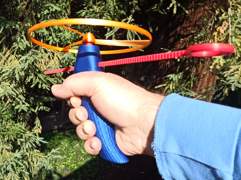
<p>I thought it would be fun to design a pullcopter toy with over-engineered features, that is, interesting improvements that aren't necessary for the function of the device, but may (or may not) improve the performance. This design makes use of three of my other designs:</p><ul><li><a href="https://www.printables.com/model/148595-gears-with-custom-cut-tooth-styles">Tilted-sinewave gear cutting</a></li><li><a href="https://www.printables.com/model/154837-ergonomic-handle-based-on-scientific-study">Ergonomic handle</a></li><li><a href="https://www.printables.com/model/159163-elliptical-blade-naca-airfoil-propeller-library">Elliptical-blade NACA airfoil propeller</a></li></ul><p>The over-engineered improvements include:</p><ul><li>Designed to assemble without tools or fasteners. The handle assembly snaps together.</li><li>Ergonomic handle based on actual anthropometric measurements of human populations, described and cited in <a href="https://www.nablu.com/2022/03/whose-hands-are-biggest-you-may-be.html">my blog article about building the handle</a>. The handle can also have finger grooves, but I don't recommend this because then it fits only one specific hand size (see below).</li><li>Custom-cut gear using asymmetrical gear teeth (smooth sawtooth using a skewed sinewave profile). The idea here is that the forces on the gear teeth are just one-way, so eliminating the symmetry decreases the pressure angle of <strong>both</strong> meshing teeth, and increases the strength of the tooth in the force direction. However, this may actually be a compromise because asymmetric teeth seem to have more rubbing than rolling surfaces, increasing the wear. The two parts using these gear teeth are small and easy to re-print.</li><li>The propeller design is described in <a href="https://www.nablu.com/2022/03/elliptical-blade-naca-airfoil-propeller.html">my blog article about elliptical-blade propellers</a>. The propeller here has a number of improvements over the usual pull-copter propeller:<ul><li>The blades are accurately twisted for constant pitch along the length of the blade.</li><li>The blade transitions through three NACA airfoil shapes from the root to the tip: NACA 9440, NACA 6412 (commonly used for propellers), and NACA 3412.</li><li>High aspect ratio blades for greater efficiency.</li><li>Elliptical wings are considered to be efficient, and the propeller blades have an elliptical profile (albeit the ellipse is truncated at the blade tip, and highly distorted toward the blade root).</li><li>The blades are swept to reduce leading-edge drag. Ideally they should be swept forward to help collimate the air-jet directly downward to minimize spread and improve thrust.</li><li>The propeller ring also uses an airfoil profile, a symmetrical NACA 0020, to reduce drag.</li></ul></li><li>Two paths for the pullcord, for pulling it with the left hand or right hand.</li><li>Tapered propeller drive cogs allow the propeller to depart in a range of vertical speeds.</li></ul><h3>Before printing the parts</h3><p>I recommend you print the "clearance_check" STL or 3MF file first. This is a set of all the parts that need to fit together, truncated for quick printing and checking. If the clearances seem too tight, you may need to adjust them in the pullcopter.scad file. There are four clearance parameters starting at line 119.</p><p>If you have unusually large hands, <strong>or</strong> if you decide you want finger grooves in the handle, you need to set the <code>handlength</code> and <code>handwidth</code> parameters to your own personal measurements. You can set the parameter <code>handle_fingergrooves</code> to <code>true</code> once you set your hand measurements.</p><p>Otherwise, see the print settings for each individual part below.</p><h3>Print Settings</h3><h4>Overall</h4><ul><li><strong>Resolution:</strong><ul><li>0.4mm nozzle</li><li>0.15mm layers for propeller, 0.20mm for everything else</li></ul></li><li><strong>Perimeters:</strong><ul><li>2 (minimum) for handle</li><li>3 for everything else</li></ul></li><li><strong>Ensure vertical shell thickness:</strong><ul><li>Disabled for propeller</li><li>Doesn't matter for everything else</li></ul></li><li><strong>Detect bridging perimeters:</strong> enabled (<i><strong>especially</strong></i> for handle and propeller)</li><li><strong>Infill: </strong>15% gyroid or cubic</li><li><strong>Supports:</strong><ul><li>Snug 0.1mm contact distance for propeller only</li><li>No supports needed for everything else</li></ul></li><li><strong>Elephant's foot compensation:</strong> 0 (can use 0.1mm for pullcord)</li></ul><p>These settings are described in the sections below.</p><h4>Drive gear</h4><p>Definitely print with a brim because the surface area on the print bed is small. Can be printed together with the pullcord from the same material, since both of them are gears.</p><h4>Pullcord</h4><p>No infill needed. The pullcord occupies the full diagonal length of the print bed and there is little room for brim or skirt material. Can be printed together with the drive gear, but the drive gear needs its own brim. To prevent the pullcord from warping, add a couple of helper discs to each end, intersecting the side with no teeth. This should keep the pullcord on the build plate. You can use a brim, but shouldn't need one with helper discs. Setting elephant foot compensation to 0.1 may help keep the teeth edges vertical near the bottom layer.</p><p>Two sizes of pullcord are included: one to fit a Prusa i3 MK3S build plate, and one to fit a Prusa Mini build plate.</p><h4>Handle</h4><p>This has two parts: gear case and hand grip. Their shapes both depend on hand dimensions and they mate together with a slide + snap mechanism. These print upside-down. Can be printed with 2 perimeters, but 3 is better, to add strength to the attachment rails.</p><p>If you need to print them separately, use your slicer to separate the parts into objects, and delete one.</p><p>Two handle sizes are included, to fit an average male hand or an average female hand. You can adjust the <code>handwidth</code> and <code>handlength</code> parameters for your hand. <code>handwidth</code> is the four-finger width with your fingers straight out and touching, measured from the base of the index finger to the base of the pinky, where the first crease of the fingers meet your palm. <code>handlength</code> is the distance from the tip of your middle finger to the first crease where your palm meets your wrist.</p><p>If you set your own measurements, you can also set the <code>handle_fingergrooves</code> parameter to <code>true</code> to get finger grooves, which cause the handle to fit only the hand measurements you specify. I don't recommend this for a toy that multiple people would share.</p><h4>Propeller</h4><p>This part may be difficult. It needs supports for angles shallower than 35° from horizontal. Use the "snug" support type, honeycomb pattern, 0.1mm z-contact distance. Print with 0.15mm layer height, 3 perimeters, zero infill. The “ensure vertical shell thickness” setting should be <strong>disabled</strong> for lightest weight.</p><p>Set a cylinder modifier around the hub with 20% cubic infill, to provide some structure connecting the drive hole with the rest of the propeller.</p><h3>Post-Printing</h3><p><strong>Important:</strong> Prior to assembly, lubricate the moving parts by rubbing a paraffin wax candle or a crayon over the drive gear bottom disc and the two bearing contacts on the shaft. Also rub some wax on all surfaces of the pullcord, including the tips of the teeth. You don't need to gum up the teeth with wax.</p><p>Insert the drive gear into the handle top. Slide the top over the handle until it snaps together.</p><p>Work the pullcord into the channel, and slide it back and forth to smooth out any rough spots. There are two channels, for left-handed and right-handed use.</p><p>With the pullcord inserted all the way, plase the propeller on top of the drive shaft.</p><p>Smoothly pull out the pullcord and watch the propeller fly away!</p><h3>How I designed this</h3><p>This is one of my more ambitious designs, as it spawned three other separate projects (gear cutting, ergonomic handle, and propeller) that I had to complete before I could even get to the pullcopter. The handle and the propeller designs each went through two major design changes, basically re-starting from scratch. Everything was done in OpenSCAD. Many failed propellers were printed - some failed while printing, others just failed to perform due to being overweight or low pitch (and in one case the pitch was reversed without me realizing it).</p><h3>Maximizing flight duration (needs testing)</h3><p>There is a "sweet spot" for the mass of the propeller ring, which is unknown for this design. A heavy ring has more inertia, causing the propeller to spin longer, but if it's too heavy the propeller cannot lift itself as high into the air. A lighter ring means the propeller lifts less weight, but the lower inertia also causes it to slow down quicker. Somewhere in between is an optimal mass for the ring to maximize flight duration. The same is true for the mass of the blades. After printing several propellers, it seems that the weight is the dominant factor, with longer duration flights for lighter-weight propellers. Wider blades don't help anything; extra width just adds weight. In fact, high-aspect-ratio (long and narrow) blades seem most efficient. On the other hand, narrow blades are not as strong.</p><p>Similarly, there is also an optimal pitch for the propeller. Higher pitch means greater thrust but also greater drag and less flight duration. On aircraft with fixed-pitch propellers, a propeller optimized for climb has lower pitch, and a propeller optimized for cruising has higher pitch. But the "climb" prop does not cruise as fast, and the "cruise" prop cannot climb well. For a pullcopter propeller of a given weight, there is an optimal pitch that maximizes altitude or flight duration. Most aircraft propellers have a pitch between (apprximately) 75%-133% of the blade length. That range resulted in a pullcopter propeller that hovered but wouldn't lift its own weight easily. The propeller in this design is pitched 200% of the blade length, which works much better.</p><h3>Version history</h3><ul><li>Version 1 (1 April 2022)</li><li>Version 2 (28 April 2022):<ul><li>Updated to correct gap between build plate and drive gear in clearance-check model, and add union() operation to make drive gear one part.</li></ul></li><li>Version 3 (9 May 2022):<ul><li>Thickened the handle attachment rails by 2 mm to prevent breakage. <strong>This makes the handle top incompatible with the previous handle.</strong> If an attachment rail broke from your previous handle top, try printing <a href="https://www.thingiverse.com/thing:5381409">this remix by kdcool</a> if you don't want to re-print a whole new handle.</li><li>Integrated finger grooves in handle (not recommended).</li></ul></li></ul><p>Category: Mechanical Toys</p>
With this file you will be able to print Way over-engineered pull-copter v3 with your 3D printer. Click on the button and save the file on your computer to work, edit or customize your design. You can also find more 3D designs for printers on Way over-engineered pull-copter v3.