Wind vane
thingiverse
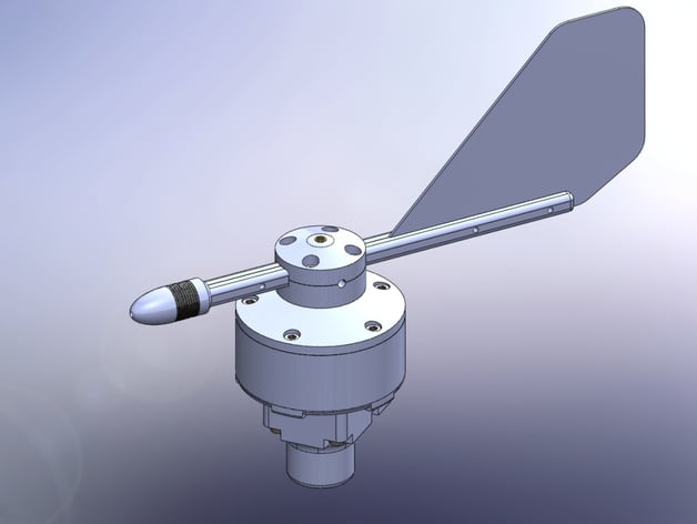
These are the plastic parts needed to build a wind vane. When used with a Yocto-Knob this thing will give you wind direction through USB. Instructions These are plastic parts needed to build an USB wind vane. They are meant to be used with a Yocto-Knob ( yoctopuce.com/EN/products/usb-sensors/yocto-knob ), but any electronics with GPIO, such as Raspberry PI or Arduino, would probably do as well. You will find here instructions for assembly. Details about electronics and programming can be found on our blog: yoctopuce.com/EN/article/how-to-measure-wind-part-2 This thing is assembled using screws and brass threaded inserts. This allows to assemble and disassemble it quickly and easily. Moreover, the final assembly is rock solid. Additional Hardware You will need some non-printable hardware to build this thing. Five 3mm LEDs as powerful as possible, e.g. L-7104SEC-J3 from Kingbright Five 3mm photo-transistors, e.g. : SFH 310-2/3 from OSRAM Five 200 Ω resistors Non insulated wire Electric wire A Yocto-Knob or equivalent A 3mm axle Two 3x10x4 stainless bearing ex: xiros® B180 from igus.com M3 threaded inserts, such as BN 1036 - DIN 16903 B from bossard.com M3 screws M3 headless screws Some 13x3 metallic washers Some glue suited for the matter used by your 3D printer (*) Optionally, a 16mm rod and a PG.M0.7GL.LN connector from LEMO. (*) If you are using ABS, you may want to try Methyl-Ethyl-Ketone (MEK). Actually it's not glue but a powerful ABS solvent allowing to literally weld parts. Tools Glue gun Fine wire cutter A pair of tweezers Various screw drivers Solder iron Mounting steps STEP 1 Make rings with the non-insulated wire. Solder the rings, the phototransistors and electric wire together in one led-holder, then do the same with the led and resistors in the second led-holder. This is delicate work, fine wire cutter and a pair of tweezers will help. Once both are working, fill the voids with hot glue. STEP 2 Place the threaded inserts with a solder iron in all the body and the hub parts STEP 3 Stack the body bottom, the led holder with the leds. Place one bearings. Force the wheel on the axle and place it. STEP 4 Stack the body and the led holder with the photo-transistors, place the second bearing in the top body and close the body. The axle must spin freely. If needed, use washers. STEP 5 Glue the the rod parts and the stabilizer. You can place toothpick in the holes for proper alignment. STEP 6 Place a threaded insert on the rod end, place the nose ring, and screw as many metallic washers as needed for a proper balance. Force the nose on head of the screw fixing the ballast. Install the rod between the two hub parts. Notice the headless screws used to lock it on the axle. You can make spacers from a brass 3mm tube, and force them into to the hub parts to make sure plastic wont bend when you tighten the headless screws. STEP 7 Assemble the body and the rotor. Optionally you can use the support. The support is designed to mount the wind vane on a 16mm rod and connect it with a PG.M0.7GL.LN connector Assembly is complete, now you need to wire it and to write the program needed to decode the axle positions. For more info on the electronics, see yoctopuce.com/EN/article/how-to-measure-wind-part-2
With this file you will be able to print Wind vane with your 3D printer. Click on the button and save the file on your computer to work, edit or customize your design. You can also find more 3D designs for printers on Wind vane.