Window Blind Remote Control
prusaprinters
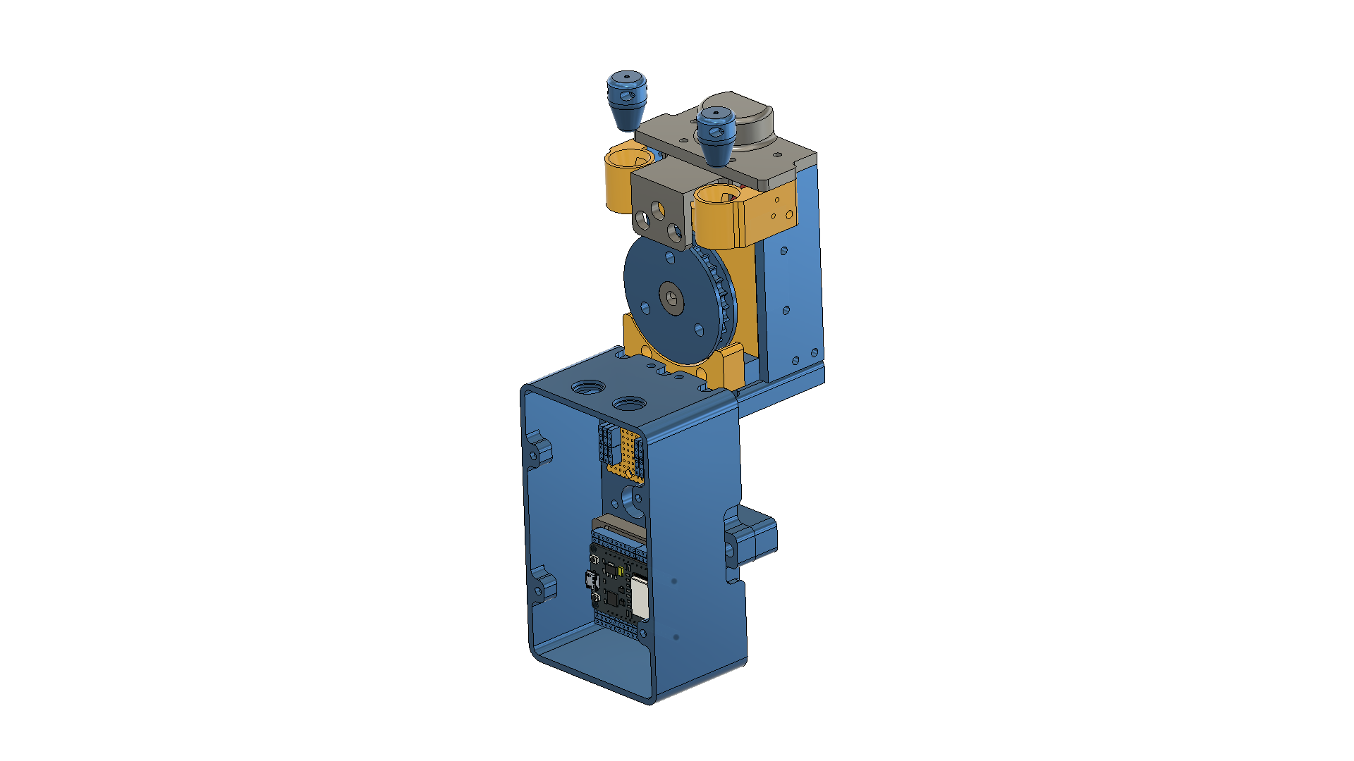
<p>This unit will adjust, open/close window blinds using remote control. Commands are sent from a mobile phone using wifi. To prevent damage endstops are provided to set the fully open and fully closed positions.</p> <p>Note:</p> <p>This project is very much a prototype, has room for improvement and not really designed to be released into the wild. However some have shown interest in making it so hopefully this all makes sense.</p> <h3>Print instructions</h3><p>The unit contains an ESP32 Devkit controller, DRV8833 motor driver, 6V 6RPM Worm drive motor, 3x leds, 2x microswitches and 2x momentary push button switches. In addition you will need brass inserts M3 x 5mm x 5mm to join components etc, M3 + M2 Cap screws, M4 hex drive long grubscrews and a suitable shaft coupler. Everything from eBay.</p> <p>Also window blind cord/chain purchased from amazon. Small rubber bands to fix couplings. I used black dreadlock bands from eBay.</p> <p>Please note:</p> <p>I create fixing holes 5.3mm diameter to accept the 5mm brass inserts. On my machine this allows easy insertion and prevents rotation. It is possible that your printer may be different so please purchase the inserts first and make a test piece to check.</p> <p>The inserts are fixed using an M3 hex bolt which pulls them into the hole. If you add a 3mm bearing under the head it spreads the load and makes it much easier to insert. If you need to reprint a piece the inserts can be gently tapped out using an M3 bolt.</p> <p>Construction:</p> <p>Cord drive wheel:</p> <p>This is constructed from 3 components. The cog wheel is printed in two parts to avoid supports and screwed together. The coupler is NOT printed, it is a standard M6 aluminium shaft coupler approx 14mm diameter. The coupler is an interference fit onto the wheel and the clamp screw holes aligned. Use 2x M4 hex grub screws through the wheel until they are visible in the coupler. This now locks the two components together and prevents rotation. Worth remembering this combination as it has proved useful for other projects.</p> <p>Main:</p> <p>Fit brass inserts as indicated in the pictures. Do not overtighten, the interference fit is to prevent rotation.</p> <p>Refer to the exploded pictures and start with the motor bracket.</p> <p>Add microswitches and guides to side panels and fix all to base.</p> <p>Rotate motor shaft so flat is facing up. Fit cord wheel, align so that pull cord passes through guides and onto wheel in a straight line.</p> <p>Attach led plate to top cover and fit to side plates.</p> <p>Attach component plate to base plate.</p> <p>Wiring:</p> <p>I have included 2x cable routes through the base to allow simple cable routing. ESP32 pin numbers in code.</p> <p>You need:</p> <p>Power Led<br/> Open Led<br/> Close Led<br/> Open Microswitch<br/> Closed Microswitch<br/> Common GND for above<br/> Manual Open push button<br/> Manual Close push button</p> <p>Motor +<br/> Motor -</p> <p>So 8 wires in total.<br/> Manual buttons are fixed to the case and wired directly to the ESP32.</p> <p>ESP to Motor driver: (pin numbers in code)</p> <p>Control 1<br/> Control 2<br/> 5V (ESP32 pin has 5V available from USB input)<br/> GND<br/> Enable<br/> Motor 1<br/> Motor 2</p> <p>Check operation of microswitches, you may need to bend the actuator arms slightly.</p> <p>Installation:</p> <p>Mounting options were limited, the window sill is plastic and I would not be popular if I drilled into it. The mounting block sits under the sill and is screwed into the wall. The main unit attaches using 2x M3 screws into captive inserts.</p> <p>You can replace the existing cord/chain which will make it neater. However it still may be worth adding to existing to prove the operation first.</p> <p>Feed around 1m chain through cord wheel.</p> <p>Pull down existing blind cord to establish fully open position.</p> <p>Back off slightly and fit end stop in left cup.</p> <p>Use cord connector to splice new cord onto existing, leave some slack.</p> <p>Cut out slack and fit inline coupler.</p> <p>Repeat for closing side.</p> <p>Misc:</p> <p>As this is a prototype I did not want to solder components to a board so I made a couple of verostrip carriers with headers. Each has a printed carrier plate to simplify installation. The headers take standard breadboard patch wires.</p> <p>The box cover is probably bigger than required but I needed plenty of space for the patch wires. If you solder direct then the height may be reduced by say 20mm. Let me know if you need a new stl.</p> <p>Software:</p> <p>Please follow this info to setup the ESP32 and allow programming via Arduino IDE.</p> <p><a href="https://dronebotworkshop.com/esp32-intro/">https://dronebotworkshop.com/esp32-intro/</a></p> <p>Remember to add your wifi details !!</p> <p>Code:</p> <p>/<strong><strong>*</strong></strong><br/> Rui Santos<br/> Complete project details at <a href="http://randomnerdtutorials.com">http://randomnerdtutorials.com</a></p> <p>Modified by Pat Cooper</p> <p><strong><strong>*</strong></strong>/</p> <p>// Load Wi-Fi library</p> <h3>include <WiFi.h></h3> <p>// Replace with your network credentials<br/> const char<em> ssid = "------------";<br/> const char</em> password = "-------------";</p> <p>// Set web server port number to 80<br/> WiFiServer server(80);</p> <p>// Variable to store the HTTP request<br/> String header;</p> <p>// Auxiliar variables to store the current output state<br/> String output21State = "off"; // power<br/> String output32State = "off"; // open<br/> String output33State = "off"; // close</p> <p>// Assign output variables to GPIO pins<br/> //const int output2 = 2;<br/> int ol = 0;<br/> int cl = 0;<br/> int mc = 0;<br/> int mo = 0;<br/> const int close_led = 12; // red<br/> const int power_led = 14; // blue<br/> const int open_led = 27; // green<br/> const int manual_close = 16;<br/> const int manual_open = 17;<br/> const int closelimit = 18;<br/> const int openlimit = 19;<br/> const int output21 = 21;<br/> const int output32 = 32;<br/> const int output33 = 33;</p> <p>// Current time<br/> unsigned long currentTime = millis();<br/> // Previous time<br/> unsigned long previousTime = 0;<br/> // Define timeout time in milliseconds (example: 2000ms = 2s)<br/> const long timeoutTime = 2000;</p> <p>void setup() {<br/> Serial.begin(115200);<br/> pinMode(close_led, OUTPUT);<br/> pinMode(power_led, OUTPUT);<br/> pinMode(open_led, OUTPUT);<br/> pinMode(manual_close, INPUT_PULLUP);<br/> pinMode(manual_open, INPUT_PULLUP);<br/> pinMode(closelimit, INPUT_PULLUP);<br/> pinMode(openlimit, INPUT_PULLUP);<br/> pinMode(output21, OUTPUT);<br/> pinMode(output32, OUTPUT);<br/> pinMode(output33, OUTPUT);</p> <p>digitalWrite(output32, HIGH);<br/> digitalWrite(output33, HIGH);</p> <p>delay(3000);</p> <p>digitalWrite(close_led, LOW);<br/> digitalWrite(power_led, LOW);<br/> digitalWrite(open_led, LOW);<br/> digitalWrite(output21, LOW);<br/> digitalWrite(output32, LOW);<br/> digitalWrite(output33, LOW);</p> <p>// test led's<br/> digitalWrite(close_led, HIGH);<br/> delay(100);<br/> digitalWrite(power_led, HIGH);<br/> delay(100);<br/> digitalWrite(open_led, HIGH);<br/> delay(100);</p> <p>digitalWrite(close_led, LOW);<br/> delay(100);<br/> digitalWrite(power_led, LOW);<br/> delay(100);<br/> digitalWrite(open_led, LOW);</p> <p>// Connect to Wi-Fi network with SSID and password<br/> Serial.print("Connecting to ");<br/> Serial.println(ssid);<br/> WiFi.begin(ssid, password);<br/> while (WiFi.status() != WL_CONNECTED) {<br/> delay(500);<br/> Serial.print(".");<br/> }<br/> // Print local IP address and start web server<br/> Serial.println("");<br/> Serial.println("WiFi connected.");<br/> Serial.println("IP address: ");<br/> Serial.println(WiFi.localIP());<br/> server.begin();<br/> }</p> <p>void loop(){</p> <pre><code> ol = digitalRead(openlimit); cl = digitalRead(closelimit); mo = digitalRead(manual_open); //Serial.println(mo); mc = digitalRead(manual_close); //Serial.println(mc); if (ol == 1) { digitalWrite(32, LOW); Serial.println("Warning Open Limit reached"); } if (cl == 1) { digitalWrite(33, LOW); Serial.println("Warning Closed Limit reached"); } if (mc == 0) { // detect manual closing switch digitalWrite(21,HIGH); digitalWrite(power_led, HIGH); digitalWrite(32,HIGH); digitalWrite(close_led, HIGH); digitalWrite(open_led, LOW); Serial.println("Closing"); delay(100); digitalWrite(32,LOW); digitalWrite(close_led, LOW); } if (mo == 0) { // detect manual opening switch digitalWrite(21, HIGH); digitalWrite(power_led, HIGH); digitalWrite(33, HIGH); digitalWrite(open_led, HIGH); digitalWrite(close_led, LOW); Serial.println("Opening"); delay(100); digitalWrite(33, LOW); digitalWrite(open_led, LOW); } if ((mo == 0) && (mc == 0)) { // shut down power and reset manual switches digitalWrite(21, LOW); digitalWrite(32, LOW); digitalWrite(33, LOW); digitalWrite(open_led, LOW); digitalWrite(close_led, LOW); digitalWrite(power_led, LOW); delay(3000); } </code></pre> <p>WiFiClient client = server.available(); // Listen for incoming clients</p> <p>if (client) {</p> <pre><code>// If a new client connects, currentTime = millis(); previousTime = currentTime; Serial.println("New Client."); // print a message out in the serial port String currentLine = ""; // make a String to hold incoming data from the client while (client.connected() && currentTime - previousTime <= timeoutTime) { // loop while the client's connected currentTime = millis(); if (client.available()) { // if there's bytes to read from the client, char c = client.read(); // read a byte, then Serial.write(c); // print it out the serial monitor header += c; if (c == '\n') { // if the byte is a newline character // if the current line is blank, you got two newline characters in a row. // that's the end of the client HTTP request, so send a response: if (currentLine.length() == 0) { // HTTP headers always start with a response code (e.g. HTTP/1.1 200 OK) // and a content-type so the client knows what's coming, then a blank line: client.println("HTTP/1.1 200 OK"); client.println("Content-type:text/html"); client.println("Connection: close"); client.println(); // turns the GPIOs on and off if (header.indexOf("GET /21/on") >= 0) { // power Serial.println("GPIO 21 on"); output21State = "on"; digitalWrite(output21, HIGH); digitalWrite(power_led, HIGH); } else if (header.indexOf("GET /21/off") >= 0) { Serial.println("GPIO 21 off"); output21State = "off"; output32State = "off"; output33State = "off"; digitalWrite(output21, LOW); digitalWrite(power_led, LOW); digitalWrite(output32, LOW); // disable open digitalWrite(open_led, LOW); digitalWrite(output33, LOW); // disable close digitalWrite(close_led, LOW); } else if (header.indexOf("GET /32/on") >= 0) { // open Serial.println("GPIO 32 on"); if ((output32State = "on") && (output21State = "on")) { digitalWrite(output32, HIGH); // enable open digitalWrite(open_led, HIGH); output33State = "off"; // flag close disabled digitalWrite(output33, LOW); // disable close digitalWrite(close_led, LOW); } } else if (header.indexOf("GET /32/off") >= 0) { Serial.println("GPIO 32 off"); output32State = "off"; digitalWrite(output32, LOW); // disable open digitalWrite(open_led, LOW); output33State = "off"; // flag close disabled digitalWrite(output33, LOW); // disable close digitalWrite(close_led, LOW); } else if (header.indexOf("GET /33/on") >= 0) { // close Serial.println("GPIO 33 on"); if ((output33State = "on") && (output21State = "on")) { digitalWrite(output33, HIGH); // enable close digitalWrite(close_led, HIGH); output32State = "off"; // flag open disabled digitalWrite(output32, LOW); // disable open digitalWrite(open_led, LOW); } } else if (header.indexOf("GET /33/off") >= 0) { Serial.println("GPIO 33 off"); output33State = "off"; digitalWrite(output33, LOW); // disable close digitalWrite(close_led, LOW); output32State = "off"; // flag open disabled digitalWrite(output32, LOW); // disable open digitalWrite(open_led, LOW); } // Display the HTML web page client.println("<!DOCTYPE html><html>"); client.println("<head><meta name=\"viewport\" content=\"width=device-width, initial-scale=1\">"); client.println("<link rel=\"icon\" href=\"data:,\">"); // CSS to style the on/off buttons // Feel free to change the background-color and font-size attributes to fit your preferences client.println("<style>html { font-family: Helvetica; display: inline-block; margin: 0px auto; text-align: center;}"); client.println(".button { background-color: #4CAF50; border: none; color: white; padding: 16px 40px;"); client.println("text-decoration: none; font-size: 30px; margin: 2px; cursor: pointer;}"); client.println(".button2 {background-color: #555555;}</style></head>"); // Web Page Heading client.println("<body><h1>Blind Controller</h1>"); client.println("<body><h2>Press Power Button First</h2>"); // Display current state, and ON/OFF buttons for GPIO 21 - Power relay // client.println("<p>GPIO 21 - State " + output21State + "</p>"); // If the output21State is off, it displays the ON button if (output21State=="off") { client.println("<p><a href=\"/21/on\"><button class=\"button\">Power</button></a></p>"); } else { client.println("<p><a href=\"/21/off\"><button class=\"button button2\">Power</button></a></p>"); } // Display current state, and ON/OFF buttons for GPIO 32 // client.println("<p>GPIO 32 - State " + output32State + "</p>"); // If the output32State is off, it displays the ON button if (output32State=="off") { client.println("<p><a href=\"/32/on\"><button class=\"button\">Open</button></a></p>"); } else { client.println("<p><a href=\"/32/off\"><button class=\"button button2\">Open</button></a></p>"); } client.println(); // Display current state, and ON/OFF buttons for GPIO 33 // client.println("<p>GPIO 33 - State " + output33State + "</p>"); // If the output33State is off, it displays the ON button if (output33State=="off") { client.println("<p><a href=\"/33/on\"><button class=\"button\">Close</button></a></p>"); } else { client.println("<p><a href=\"/33/off\"><button class=\"button button2\">Close</button></a></p>"); } client.println("</body></html>"); // The HTTP response ends with another blank line client.println(); // Break out of the while loop break; } else { // if you got a newline, then clear currentLine currentLine = ""; } } else if (c != '\r') { // if you got anything else but a carriage return character, currentLine += c; // add it to the end of the currentLine } } } // Clear the header variable header = ""; // Close the connection client.stop(); Serial.println("Client disconnected."); Serial.println(""); </code></pre> <p>}<br/> }</p> <p>End of text</p>
With this file you will be able to print Window Blind Remote Control with your 3D printer. Click on the button and save the file on your computer to work, edit or customize your design. You can also find more 3D designs for printers on Window Blind Remote Control.