Window Chain Actuator
thingiverse
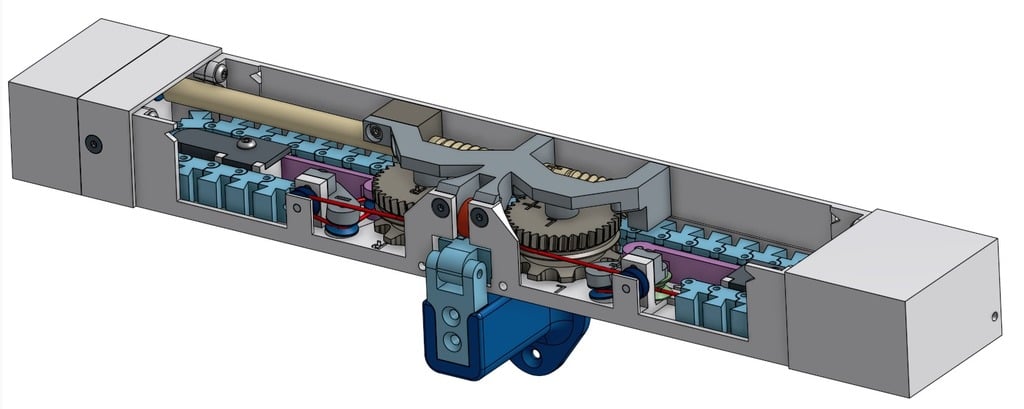
I Made a Window Chain Actuator to Automatically Control Room Temperature in Winter I created a window chain actuator that automatically controls room temperature during winter. The actuator uses a 28byj-48 12V stepper motor, a Microchip PIC16F877A microcontroller, and a Dallas DS18B20 digital thermometer. The Stepper Motor The 28BYJ-48 is a 5-wire bipolar stepper motor with a holding torque of 2.8 kgf.cm. It has a step angle of 1.8° and can rotate up to 1500 steps per second. The motor is controlled by a L298N dual H-bridge driver IC. The Microcontroller The PIC16F877A microcontroller is an 18-pin RISC-based microcontroller with a clock speed of 4 MHz. It has 192 bytes of EEPROM, 256 bytes of RAM, and 13 I/O pins. The microcontroller is programmed using the MPLAB X IDE and XC8 compiler. The Thermometer The Dallas DS18B20 digital thermometer is a high-precision temperature sensor that measures temperatures between -55°C to +125°C with an accuracy of ±0.5°C. It communicates with the microcontroller over a 1-wire interface. The Actuator Assembly The actuator assembly consists of a stepper motor, a gearbox, and a chain drive system. The gearbox is a helical gear reducer that reduces the motor speed to 12:1 ratio. The chain drive system consists of a sprocket wheel attached to the gearbox output shaft and a toothed belt that connects the sprocket wheel to a moving chain. The Moving Chain The moving chain consists of 36 links made of nylon material with a thickness of 2 mm. Each link has a diameter of 10 mm and a pitch of 20 mm. The chain is attached to a center holder that is fixed to the window frame using screws. The Stepper Shaft The stepper shaft is a stainless steel rod with a diameter of 8 mm and a length of 100 mm. It is attached to the gearbox output shaft and drives the moving chain. The Helical Gear Right The helical gear right is a high-precision gear reducer that reduces the motor speed to 12:1 ratio. It has a gear ratio of 10:1 and a backlash of <5 arcmin. The Electronics The electronics consist of a L298N dual H-bridge driver IC, a PIC16F877A microcontroller, a Dallas DS18B20 digital thermometer, and a JST XH connector for connecting the actuator to the window frame. The microcontroller is programmed using the MPLAB X IDE and XC8 compiler. The Code The code for the actuator is written in C language and uses the MPLAB X IDE and XC8 compiler. It includes functions for reading the temperature, controlling the stepper motor, and monitoring the moving chain. The Libraries The libraries used for the actuator are: * AnalogMultiButton: a library for reading analog inputs from multiple buttons * DHT_nonblocking: a library for reading digital temperatures from the Dallas DS18B20 sensor The Schematics The schematics for the actuator can be found in the attached PDF file. Good Luck! UPDATE 2019-04-26: added redesigned chain for easier print "Chain Whole V3" and fixed bug, both sides needs equal number of chain parts, old design has one missing chain part. Old design for some people fused too much, couldn't get it separated. Just break off orange parts. New design needs very little to no post processing. Explanation could be found in photo. UPDATE 2019-08-16: added schematics and code. For "Opened" and "Closed" switches use Snap-Action Switch. I use switches like these https://www.pololu.com/product/1403 but bought in local electronics shop. Connect switch side pins, middle pin not connected, otherwise you need to change code. UPDATE 2019-11-07: added missing files for Steper Shaft and Helical Gear Right
With this file you will be able to print Window Chain Actuator with your 3D printer. Click on the button and save the file on your computer to work, edit or customize your design. You can also find more 3D designs for printers on Window Chain Actuator.