Wireless PIR Sensor Enclosure
thingiverse
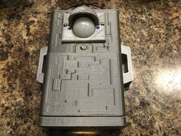
This enclosure features a high-tech PIR shield, precision-engineered circuit board, and advanced battery compartment with secure battery door. The circuit board is specifically designed for an Adafruit Pro Trinket (5V) and a cutting-edge RFM69HCW Transceiver Radio Breakout. The exterior of the enclosure boasts a futuristic digital camouflage pattern and ergonomic side handles for easy mounting using small bungee cords. The PIR cover has a built-in sun shield that also protects the sensitive PIR lens during transportation. As always, I've included the 123D design files for modification purposes to meet your project needs. This is part of a larger innovative project still in progress. It's being shared with others who may be looking for an enclosure for similar components. Check out http://www.instructables.com/id/Sensor-Array-and-Monitor/ for more details on this project. Thumb Screw Heads for the battery cover can be found here: http://www.thingiverse.com/thing:1764416 Digital Camo Stencils for painting can be found here: http://www.thingiverse.com/thing:1765630 Print Settings: Printer Brand: Printrbot Printer: Simple Black Rafts: No Supports: Yes Resolution: 2.6 mm Infill: 30% Post-Printing: Remove all support material and carefully clean up any artifacts. All interconnecting parts should be thoroughly cleaned and tested before final assembly. Holes should be checked and drilled to the correct size if necessary. Here's an Instructable I created on custom circuit boards: http://www.instructables.com/id/Custom-Circuit-Boards/ Circuit Board: Assemble components on the circuit board. The Pro Trinket can be attached using small screws, but I used melted filament on each end for a secure connection. The RFM69HCW is secured to the circuit board with super glue on contact points. Wire wrap wire and wire wrap tool are used for wiring. The battery clip is soldered in place. Enclosure Top: Cut out the hole for the PIR sensor. The print has a thin layer with a wedge-shaped support for the battery cover nut holder. Auto supports didn't work well, so I added these supports manually. They may be challenging to cut, so use a sharp knife and exercise caution when cutting this out. Place a 6-32 Nut into the battery cover slot on the top and two 6-32 nuts in the hex indents on each side for the side handles. Secure them with a few drops of super glue. Slide the circuit board into the enclosure top slots. PIR Enclosure Cover: Attach the PIR to the cover using fasteners. Be cautious not to short any components due to the proximity of holes. I used melted filament on the ends to secure the PIR to the cover. The PIR and cover can be assembled to the Enclosure Top using small metal screws. Enclosure Bottom: The bottom consists of the battery compartment and battery door. The enclosure is designed for an 8 AA battery pack from Radio Shack. Test fit the battery door. It may require some filing of the edges so it works smoothly. There are hex indents for two 6/32 nuts. A few drops of super glue will hold these nuts in place. Press the enclosure bottom to the enclosure top. These do not need to be glued, as they are held together by the side handles. The battery door can be secured with a 6/32 x ¾” screw. Handles: The two handles are screwed to the sides using 4 6/32 x ¾” screws. The handles also secure the enclosure top half and bottom half.
With this file you will be able to print Wireless PIR Sensor Enclosure with your 3D printer. Click on the button and save the file on your computer to work, edit or customize your design. You can also find more 3D designs for printers on Wireless PIR Sensor Enclosure.