Working Stargate with Arduino Control
thingiverse
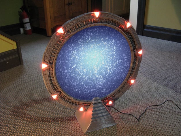
Here's a formatted version of the text: **Congratulations! You've Built Your Own Working Stargate!** This guide will walk you through assembling your very own working Stargate. This is a challenging project, but with careful following and attention to detail, you'll have it up and running in no time! **Assembling the Stargate:** * Print and glue on the Back pieces. The Back pieces are offset from the Middle pieces, so they should line up so that the glue joints of the middle pieces are in the middle of each back piece. * Congratulations! You've assembled your Stargate! **Printing the Base:** * I printed all of the Base pieces at 0.3mm layer height to decrease the print time. * Print your main Base piece! This one is going to take a long time. Mine took 11.5 Hours at 0.3mm layer height. * Once you have your Base printed, print the sides and Top Cap and make sure that they will fit onto the base. **Adding the Stepper Motor:** * Print out your Gear that will fit onto the Stepper motor, and slide it onto the drive shaft of the Stepper. * Now slide the Stepper motor into place, and secure it by screwing it to the base structure through the hole in the gear. **Testing the Gate:** * For testing purposes I suggest leaving the sides off of the base for the first few tests, the sides do add some support to hold the gate up, so you might have to carefully hold the gate upright for your initial testing. * Slide the Assembled Gate down into the base so that the teeth of the Sybol ring intersect with the teeth of the gear on the Stepper motor's shaft. **Programming the Arduino:** * Upload the provided Arduino sketch, DialingSequence.ino, to your Arduino. * Connect the Stepper motor to the motor shield, and connect the Neopixels to the 5V, Ground, and Data to pin 6 on the Shield/Arduino. **Additional Tips and Precautions:** * Be sure that you install the power jumper on the motor shield, and that you are using a wall wart of sufficient power to power your stepper motor. (12 V 1 Amp that I used was sufficient) * Do NOT power the Arduino with the motor shield connected to the stepper solely from your computer's USB port. This could cause damage to your USB bus as the Stepper is intended to work on 12V, and may draw more current in spikes than the 500 mAh that computer USB ports are rated to provide. **Final Assembly:** * Once you have tested the Gate in place on the Stepper motor, you can install the Arduino & motor shield into the holder in the base, and route your wires so that they won't get caught in the gear when it spins. * Then you can install the sides on your base, slide the Gate into place and snap the top cap into place! **Removing the Stargate from the Base:** * If you need to take your Stargate back out of the base, you will have to release the side's pins from the base, then roll the stargate to one side, sliding the side down until it slides off of the Chevron piece and can be pulled off. Then repeat the process for the other side. Congratulations! You've built your own working Stargate! I'm more than happy to help with any questions or modification suggestions anyone has, message me or leave a comment on this thing and I'll get back to you as soon as I am able (Though it might take a little while, I won't be checking Thingiverse every day!). All credit to Glitch for the incredible design of the Working Stargate! All I have done is merge some things together, and alter the base to fit an Arduino and Stepper motor (And wrote the Arduino sketch). Enjoy!
With this file you will be able to print Working Stargate with Arduino Control with your 3D printer. Click on the button and save the file on your computer to work, edit or customize your design. You can also find more 3D designs for printers on Working Stargate with Arduino Control.