X-120 - 2 Inch "Monster Whoop" Micro Brushless Racing Drone Quadcopter
thingiverse
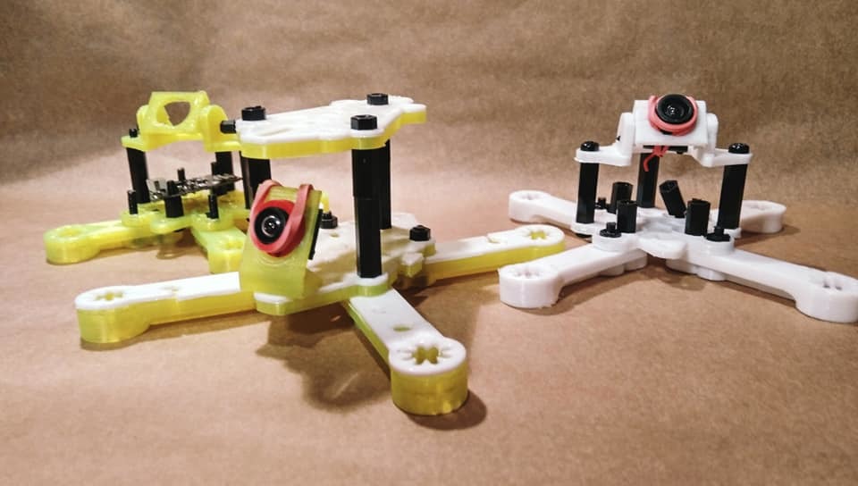
**Update - 13.09.2018** - 19 x 19 Camera Mounts Added Clearance & Adapters Note: This mount is internally cleared for 20 x 20 mm to ensure a clean fit for the camera. The mount can easily be bend to accommodate for any looseness and or you can use thin washer to resolve any issues if you encounter any. Picking the right file: There are several files here, they are as follows: 1. RunCam 19 x 19 Mount - Has a M2 hole on each side to mount 19 x 19 cameras or the provided adapters. 2. RunCam 19 x 19 Mount - Has M2 slots on each side to mount 19 x 19 cameras or the provided adapters. 3. Drop Head RunCam 19 x 19 Mount - Is labelled as such and is smaller than the other mounts. It is such that you should be able to now mount off the roof. 4. Universal Camera Adapter - By looping a rubber band around the front of the lens, twisting, pulling behind and over your camera and back onto the lens will secure your FPV camera. This is suitable for Tiny Whoop style cameras and offers adjustable tilt. The lens is cleared for 13.8 mm lenses. 5. Universal Camera Adapter TPU - This is the same as the above file with a smaller lens opening. If printed in TPU you can push fit in your camera. The mount should stretch and grip it. If you have difficultly carefully and safely cut a small slit to expand the hole. Print Advice: Place the piece on the bed so that when looking directly down it appears as a C or a U. You should have the print lines running along the long edge of the piece where the camera bolts in. For the adapter print vertically with the lock points point up off the bed. Files have been updated and included. Separate files can be found at: https://www.thingiverse.com/thing:3098162 real_darKing kindly made and shared an attractive mount to use on my frames. You can check it out at: https://www.thingiverse.com/thing:3094068 **Update: 11.09.2018** New RunCam 19 x 19 - Some users kindly reported that they were having issues with fitment of their RunCam cameras. This new mount has added clearance and should now clearance adequately. It mounts to the frame in the slot with M3 hardware. For the most strength, print so that the mount: 1. Appears like a C or U flat on the bed. 2. Has the layer lines running up the vertical edges with camera mount holes. real_darKing kindly made and shared an attractive mount to use on my frames. You can check it out at: https://www.thingiverse.com/thing:3094068 You can join the Facebook group at: https://www.facebook.com/groups/254825821981391/ **Update: 10.09.2018** **If you would like to use a Magnum Mini Stack (as in the Emax Babyhawk R) you will need to use the M2 to M3 adapters. You can mount via the arm holes or by rotating the stack to have one corner facing forward like a Tiny Whoop.** **Adapters: https://www.thingiverse.com/thing:3093369** **X-120 - Design Points & Spec In Full:** True X 120.1 mm frame with perfect balance. Fully modular: Arms are easily detachable with the removal of two bolts. Multi-config: Standard, Pusher, Puller & Split Front/Rear. Motors: 11xx in M2. Propellers: Anything up to 2.5 inch will fit with clearance. Stacks/4 in 1 ESC: 16mm x 16mm in M2 & 20mm x 20mm in M3. **Active Geometry Concept:** I’m a guitarist and if you play an instrument you know that the proportions of the instrument are key to the sound. Simplest example being a pitchfork, that resonates at a specific frequency due to its shape and density. I considered that if you design the frame proportionally you should be able to cancel out unwanted vibration in the same way a noise cancelling headphone works. Additionally, it should allow stresses to be routed in such a way that components are not damaged and to also importantly add inherent strength. For fun, if you your splicer software put an excessive number of walls you can actually see the lines of how the stresses and vibrations should be routed. This is particularly noticeable in general if you print in a translucent material and gives a very cool effect. This is just something I noted from my observations in my designs and I wanted to work with and test for proof of concept. I call this Active Geometry. **X-120 – Build Guide:** To be able to build the X-120 successfully you need to understand one key thing, that this drone has no strict form. The parts are made so that different combinations produce different style frames with different characteristics from the same parts. To build your X-120 you must first familiarise yourself with the parts and the ways in which you can combine them. Once you are familiar with the parts and the general build concept you can get going. 1. Bottom Plate – This is the main plate that you will use to bolt the quad together. The arms will lock to this piece and so will your components. The slot in the bottom plate is to accommodate the camera mounts, the idea being that you can slide the mount back and forth to suit your camera view and camera size. This plate also doubles as the top plate. 2. Lite Top Plate: This was created to offer a slightly lighter top to the quad and to give it a nice appearance. If you want to top mount your battery then it would be advised to use a second bottom plate for the top plate. 3. Arms: The arms of this quadcopter come in two types, plate (flat piece) and tri-beam reinforced. a) Tri-Beam Arm: This is one file and is the standard arm for this quadcopter. b) The plate arms come in three thickness designations, 1.1 mm, 1.7 mm and 2.8 mm. Originally my first quad, the X-132, had plate style arms in 2.8 mm. I started finding that regardless of the material these plates were prone to cracking due to their inflexibility. Experimenting I found that in basically all materials if you print several, separate layers and stack them (with or without glue) that they are structurally stronger since they can flex and this absorb some shock impact. I then started to take this a step further by using a mix of plastics and stacking them in open and closed face “sandwiches”. I have had great success with PLA/TPU/PLA (1.1 mm respective) and I postulate that the same with PETG instead of PLA will be even more resilient. The benefit of this is that the PLA flexes enough to be functional and durable and if a it gets broken the TPU stops the motors from being torn off. Apart from adding strength, this also meant that I could make some truly cool looking combinations of colours to make my quad really stand out. The 2.8 mm plates will be sufficient for solid plate pieces and then you can combine different layer thickness in different numbers to get the characteristics that you want. You can also like me, experiment with different plastics to blend characteristics. On a practical basis, using these thin “plates” you can make a quad that resembles one made from flat carbon fibre pieces, but more importantly it means that you can print very thin TPU plates for example and soft mount various parts of the quad for example if you have a very sensitive F4+ flight controller. With regard to arm mounting you will need to use two bolts, one of which will go into your stack. You will need longer nylon bolts for this in M2/M3. If you do not have these you can probably rotate your stack and use shorter bolts. With regard to flight controllers and vibration interference there is a two-fold dampening by way of the plastic itself and also the geometry which will be explained below. I use an F3 class board with ZERO issues, you should not have any issues with an F4+, if you do you can soft mount the arms to your heart’s content with a bit of foam tape or a piece of TPU. 4. Multi-config - This frame allows you to build in: a) Standard config. b) Pusher config. c) Split config. To do this you will need to likely use two bottom plates to mount arms on the roof of the quad. 5. Camera Mounts: All my drones share common parts, this means that the camera mounts can be interchanged between all of them, the same goes for stack plates and shims. There are 3 main types of camera mount: a) Universal camera mount: This comes in 10.8 mm and 12 mm lens sizes and mounts with an M3 bolt. To secure you camera, pass a rubber band through the hole with one half in front and one half sticking out behind. Pop the camera through the hole, twist the band once and loop over the lens. Then pull the other half over the camera and again over the lens to secure. You can do this sideways or vertically. Look at the pictures if this is unclear. These mounts come in a short and a tall version and are in 5-degree increments. b) Adjustable camera mount: This is from the X-82 and allows you to do as above but to use the (19 x 19) Run Cam Micro style camera mount to mount your whoop style camera but with the ability to change angle. Mount holes are in M2. c) Run Cam Micro (19 x 19) Mount: This mount takes 19 x 19 Run Cam style cameras and comes in a tall and short version. Hardware is in M2 and the frame mount hole is in M3. 6. Stack plates: The stack plates are so that components that do not have mount holes can be mounted to them with the use of foam tape or a very thin rubber band. This helps to secure and protect components and to also neaten up your build for wiring and aesthetic purposes. I use the Run Cam TX200 and I have specially designed a plate so you can screw this with M2 bolts using the recesses in the sides. 7. Soft Mounts & Shims: Depending on the material that you use to print these, these can be either shims or soft mounts (or both). There are different thicknesses for you to choose from so that you can get the best fit for your motors. 8. Motor Mounting: People argue that holes are better than slots. I disagree completely. My frames are to be universal and future proof (as far as possible) so this takes that into account. Even within 11xx motors there are different screw sizes and also different mount diameters and styles. Additionally people often strip their mount holes for the motors and this can be a serious problem if you have a limited set of holes. Secondly holes are weak points and if you crack one hole, the arm is wasted. Having a slot means that in the unlikely event you do crack a slot (normally you will snap an arm first) you can at least rotate your motor and bolt it back in. Secondly people don’t realise that all motors don’t have wires coming out from the same side, which can be a serious problem if you have not got correct holes mounts as it leaves the weak point of the wire exposed. **YOU MUST USE AT LEAST 3 BOLTS FOR YOUR MOTORS! USING 2 BOLTS WILL CAUSE A MID AIR MOTOR DETACHMENT IF YOU ARE NOT CAREFUL!** I generally think that for the sake of a 0.5g bolt per arm you should risk your quad, Lock-tite or no Lock-tite. I have had this happen in “bolt hole” arms using 2 bolts and despite good advice many continue to do this. You will have to use three bolts whether you like it or not. You can thank me when you don’t see a motor fly off in front of your camera. 9. Be free: I made these frames specially so that they could be totally customised and could accept additional parts easily. This is why I have left holes in the top plate for accessory mounting or for you to run your antennas through. If you want to put in an LED light bar, or a buzzer, or a GPS, you know that you can use any of the standard mount holes provided and just quickly and easily sketch something up for yourself. Similarly, if you want to have holes instead of slots or just want to make the design specific to you, I have thought of you in advance. The shapes are relatively easy to modify and customise to your needs. 10. Fun: My aim was to make a frame that would let people have fun with their builds and let them build to their imagination. **Flying advice:** 1. Plastic frames are not carbon frames, its easy to forget that when you are flying. 2. When you first get it into the air, treat it gently like a whoop until you get used to it. Secondly, not many frames are designed to balance perfectly or are actually “true X” and if you are not used to this it might feel a little strange at first. 3. I would generally advice to bottom mount a battery for the longevity of the frame and arms and to generally at first treat it like a whoop. Of course, once you are proficient with the frame mount as you wish. 4. Plastic frame quads will protect your components very well, particularly from current and voltage spikes that normally kill components during crashes. Secondarily the frame breaking absorbs a great deal energy which would otherwise damage your components. The frames are designed to fully enclose the key components of the drone so you should hopefully enjoy parts that last for a long time. 5. If you want to build an absolute monster I would suggest using 3s-4s and 11xx motors. However I would also advise that if you do anything above 2s, be a careful, seriously, this will seriously haul ass and then some. 6. ALWAYS CHECK FLYING REGULATIONS AND RESTRICTIONS LOCAL TO YOU BEFORE ATTEMPTING TO FLY YOUR CRAFT. **Originality of Design** Of key importance to me is that my designs are original works. I always make my designs from scratch and try and make them as distinct as possible. I want to my my frames the best that they can be. **Legal Disclaimer:** In no event shall I the designer be liable for any direct, indirect, punitive, incidental, special consequential damages, to property or life, whatsoever arising out of or connected with the use or misuse of any of my designs. In using my work you acknowledge that any and all liability is with you the user. You use this design at your own risk and are responsible for any consequences as such. **With Love - Karamvir Bhagat**
With this file you will be able to print X-120 - 2 Inch "Monster Whoop" Micro Brushless Racing Drone Quadcopter with your 3D printer. Click on the button and save the file on your computer to work, edit or customize your design. You can also find more 3D designs for printers on X-120 - 2 Inch "Monster Whoop" Micro Brushless Racing Drone Quadcopter .