X-ends and X-carriage for accurately printing with Mendelmax/Prusa
thingiverse
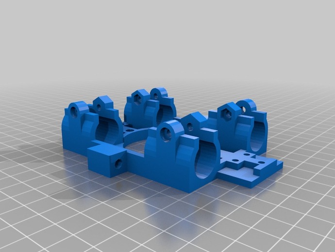
Consider this: if you put a horse in front of a car where would you rather have it pull it? Right now most X-axis designs that are using cheap components are not allowing real accurate prints. This one has the intentions to do exactly that. So it addresses many issues around X ends for Mendelmax/Prusa type designs enabling ACCURATE PRINTS. All parts needed are there and seem to work nice together. As a good observer can see, i've heavily modified some of the Kuehling designs, basically placing the belt from outside the Xaxis smooth rods to the inside just running over the X-carriage platform by about 2 millimeters and also the same amount away from the extruderplastic/aluminium plate. Todo: Testing the components in my mendelmax When it works ok i can modify it from alpha to release status. Until then consider this modification work in progress right now. Todo: GT2 belt clamp WORKING STATUS FOR : T2.5 + aluminium pulleys with 16 teeth. Though it might seem so, it uses hardly more plastic than the Kuehling designs do and in case of the X carriage it's less. Note that this gets caused by using rod distance 44 mm rather than 50 mm, which is possible as the belt attaches in between the rods rather than outside the rods. 44 mm gives a lot of space around the extruders, smaller distance is possible! With the belt attached nearby the center in between the rods, a huge rod distance no longer is a necessity; the 50 mm was a result of a historic poor design. Update 10 may: after printing a bunch of objects - i don't ike the idler design. It does work ok - yet it produces a high scraping sound i don't like. Admitted i hadn't put oil inside, so going take a look at redesigning that part using somehow a bearing. Might get the entire structure for all parts a few millimeters higher possibly as a bearing is a huge thing to fit in there. To be continued... Update 7 may: The STL of the Carriage should be mirrored, as right now it only works with the motorend facing the motor of extruder; of course mirroring extruder also works - maybe i'll try that as i need to update it anyway to win back more of the build platform. After toying trying to get it to work ok here, as i stupidly used wrong glue for idler-end and ok glue for motorend (resulting in different tolerancesand diff way it been glued in - doh), it seems that there is many ways yet left to optimize the extruder and way how beltclamp is located (as that eats massive space) of the X print area. Update 5 may: This plastic seems a MASSIVE IMPROVEMENT of the Kuehling designs. Measured the Z-axis swing to be improved by factor 5. At 15 CM distance from 5 mm to 1 mm (swing to one side in both X as well as Y direction), this while still using cheap components. The motorhang of the motorend needs to be at least 2 millimeters higher. Is easy to live with using some spacers for now. Will update the STL. Update 1 may 2013: all the latest files uploaded to here. Small changes also in the Idler end and Motor end to give it a better fit. This plastic should work. Individual component testing has been performed! "only" thing todo now is to test in my mendelmax how accurate it can print! Update 23 april: the X end idler improved to use M5 bolt and a pulley for the belt. No bearing needed! Update 21 april: the X end idler been uploaded (not yet tested well yet over here). Update 17 april : all the SCAD files have been updated and the STL as well. The thing is in alpha now. XaxisAlpha3 (repaired).stl is the latest. The repaired was added by netfab fixing it. Many small fixes and improvements. This is the Porsche for the poor. UPDATE 15 april - the latest design uploaded here and again fixed with netfab. Did do many small changes. Most in order to save plastic. April 14 design was after printing in orange PLA with 45% infill 70 grams (+5 grams for motorplate). Design should work now for the gear i've got here. Still to do: make some hole to attach solidly the X axis rods, probably going to be a variation of Jonas Kuehling, yet then upside down as the weight pushes the rods down, so not going to remove material there. Gear i've got here: M8 nuts having wrench size 12.85 mm note that the rod distance between the 2 smooth rods is 44 mm here, default in most designs it's 50 mm - yet here the belt runs from the center of the X carriage so no problem. UPDATE 14 april 2013 - fixed the STL with netfab and it prints ok now. Note it looks maybe tad more primitive right now. Also added another millimeter on top of it, which i will change later to have it split that. the "repaired* stl is the one you want to print for the X axis for now. to do: I'll modify the entire Jonas Kuehling design there soon - especially the way how it clamps the X smooth rods - as right now there is a huge difference in angle for the X carriage depending upon how tight or not tight you put in the nuts and bolts into the X ends - which is no good. This is the X axis using cheap 8mm smooth rod and cheap 8mm threaded rod. Additional modifications: the 2 nuts you have to glue in are at a larger distance, taking care the Z-axis should swing less if you glue the nuts in the correct manner into it. Also modified the attachment of the smooth rod to the threaded rod. It's giving the Z axis less swinging space. possible other modifications in future to this design: the plastic thickness on top of the X axis rods is not much, intend to make it thicker a tad, say 1 millimeter maybe 2. Right now that weight of what is it a kilo or so, gets carried by 2 X-axis ends having just very thin layer of plastic carrying it. todo: finding the link to the original X axis plastic i started with which is from Kuehling 'brothers'. From weight design a good design - from accuracy a disaster of course the Kuehling designs - hope to correct that with this plastic! Instructions Current design works when you have 2 pulleys as shown in the photo T2.5 with 16 teeth GT2 version i'll produce ASAP You need to print 6 parts using 5 stl's here and from the belt clamp you need to print 2. Mirror the carriage in CURA or Slicer as mirrored it will remove less of build platform. Current shape only works facing motorend. Of course mirroring extruder plastic also works fine :) Print the belt clamps at slow speed like 20 mm/s or SLOWER especially if you've got not too great thing as a printer. Over here in the printer NOT using this plastic yet the original Kuehling designs, there is no way to print anything fast. In that mendelmax i print the X ends at 45 - 50 mm/s using a 0.35 nozzle set at layer thickness 0.2 mm (which is the max For 0.35). That takes 5-9 hours or each component and 1+ hour for the beltclamp (which prints at slower speed) Make sure that the belt goes fine into the beltclamp, otherwise use a knife to cut away plastic so that the belt goes fine into beltclamp, realize these X ends and X carriage and clamps are all calculated to work precise to the millimeter. If belt doesn't go entirely into beltclamp it isn't perfectly level lines the belt-end. It will be 2 millimeter above printbed when installed ok (it is here as well). Especially glueing in the M8 nuts into the Xends is an important thing to do ok! For those not experienced doing that i'll give more instructions how to do that! For the motorpart you need to print it in 2 parts and glue the motorcap onto the motor-X end to mount a NEMA17 motor to move the X axis. Same thing for the belt clamps or the X carriage. Note that if you want to attach the belts in a different manner, that can be done! Please note that one can also glue the beltclamps onto the X carriage and afterwards remove the 3 m3 bolts and nuts! Note that this X-end focuses upon accuracy of printing, the disadvantage is it removes a small amount (up to 1 cm) of the build platform. Obviously moving the heatbed a bit will solve this. Still to come as of now: the modified X-carriage to attach to. The current dimensions are for a pulley which with belt around it, measuring the belt diameter (outside) around pulley is roughly 14 mm. Actually in this case that's a T2.5 aluminium pulley (if you want more accuracy no way to use self printed pulleys) yet a GT2 also works and any pulley will work as long as its diameter is under 34mm. In fact there shouldn't be accuracy differences between T5/T2.5/GT2 much with these X-ends. Note that you need 2 pulleys. One for the motor-end and one for the idler-end. In the SCAD file you just need to modify 1 parameter to move the motorplatform a bit more inwards if your pulley+belt around it has a larger diameter than 15-16 mm. If you don't feel happy doing without bearings at the idler, you can also replace the pulley there with a bearing having a center hole of 5 mm. Preferably one with an outside diameter of 11-12 mm as otherwise you will need to move the idler a bit to the left or right. Really make sure your threaded rod of Z axis is completely parallel with the smooth rod next to it, otherwise this plastic might backfire. Please note in case this wasn't clear yet that you lose a few centimeters from the X part of the buildplatform. Now i couldn't care much for that yet for a first incarnation of this plastic - will optimize that later on a tad - maybe. Note2: deliberately the X axis rod space is having a tad more space than most Xends here. Idea is to install the entire Xends and X axis and X carriage without having the smooth rods tightened yet, they should easily move through the X-end plastic. Should be one of your last actions (before probably installing the belt clamps with the belt inside) to tighten them as otherwise stress could get onto the smooth rods of X-axis.
With this file you will be able to print X-ends and X-carriage for accurately printing with Mendelmax/Prusa with your 3D printer. Click on the button and save the file on your computer to work, edit or customize your design. You can also find more 3D designs for printers on X-ends and X-carriage for accurately printing with Mendelmax/Prusa.