X & Z Axis Test Print "Are your wheels adjusted?"
thingiverse
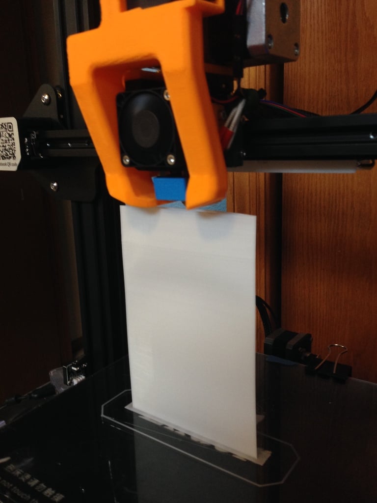
I inadvertently created a test print that helps you visualize whether your X and Z axis wheels are adjusted correctly. I was designing a print to test the Z axis layer consistency with all my “Dual Z” printers. First of all, prior to this test, my prints were printing beautifully. Plus, my calibration test cubes, Benchy’s, and Cali Cats were flawless. I never noticed these imperfections in any of my prints. This new file test prints a 100mm flat, single layer wall, parallel to the X axis 200mm tall. When I printed the first test, I noticed strange striations in the X surface. All the Z layers were consistent. The ridges can just barely be felt with your finger. I took the shot with the light at a sharp angle to show the ridges clearly. Here is a picture of the 100mm surface Since the imperfections were in approximately the same spot with each layer, I assumed it was in the X axis. I decided to tighten the X carriage by just a hair. I tightened the X carriage wheel adjusting nut by maybe a 1/32 to 1/16 of a turn. I checked to make sure that the carriage still ran back and forth well on the X rail. My next test print, after tightening the carriage, solved all of the minor imperfections in the face of the print. I theorize that the carriage was just loose enough to telegraph the dust, wheel imperfections, and rail imperfections into the print face. I think I never saw these imperfections because of the contour of my usual prints and the randomness of the ridges. They are far enough apart that the 100mm flat, single wall test print was the only way to see them. Here is after the carriage adjustment My Z layers were totally consistent all the way to 200mm, and the flaws that were present in the original test are gone. You print this as 1 wall vase mode. Keep your Z seam to the back arc so it doesn’t show in your front face. If your X carriage is loose, it will show up fairly quickly in the front surface. If you see Z banding, use the print to estimate the height on your Z rails to see if you have wheel binding at those points. Here is a youtube video of the print.
With this file you will be able to print X & Z Axis Test Print "Are your wheels adjusted?" with your 3D printer. Click on the button and save the file on your computer to work, edit or customize your design. You can also find more 3D designs for printers on X & Z Axis Test Print "Are your wheels adjusted?".