XL 7-segments Digital Clock/Thermometer
thingiverse
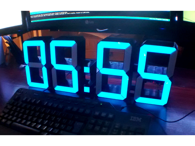
Arduino Nano + DS3231(ZS-042) + 30xAPA104-LED-Strip based digital clock/thermometer The numbers are 195mm (7.8") high, making it easy to fit one digit in most printers, the HH:MM version is 580mm (23") wide. The clock is modularized, making it easy to create a HH:MM:SS version configurable in the code. There are three case parts: the last digit with cap (1x), a normal digit connectable to the next right (3x or 5x), and a dot-case (1 or 2x). Additionally, there are four types of diffusor-inlets: A (top/bottom), B (upleft/downright), C (upright/downleft) and D (center) and one for the dots. The last digit case contains space for the two boards (Arduino Nano and ZS-042). As strip can be used all WS2811, APA104 or Neopixel kinds. I prefer the 3-wire solutions since soldering 30(or 46) interlinks is a lot of work. The digit cases can be screwed against a large beam with M3 screws directly driven in the back to give everything better strength. Wiring Instructions: Internally, the line in the digits follow the pattern: -2-, 1 3, -0-, 6 4, -5-. Just connect the Arduino GND, +5V and DI of the beginning of the strip and go from 0 in the smallest (far right) digit up through the whole clock. Just three wires through all the digits in the number. Hint: Soldering the ~6cm bridges between all seven digits of a number adds a longer triple to the end, fiddles the wires through the holes, solder them together and finally sticks the LED-strip-parts inside the gaps in the cases. BOM: 1x Arduino Nano, 1x DS 3231 (case fit for a ZS-042 board), 1x 1m APA104/WS28** 30LED/m LED-Strip (or .5m of 60LEDs/m), (one can use 1m of 60LEDs/m to use a pair for each digit to make a brighter one), ~200g colored filament for the frame (it should be optically dense) for three digit-cases, one end-case and one dot-case, ~150g white filament for seven inlets each number (there are kind of different white filaments around, I choose one that is a little less dense, lets more light shine through but still hides the dot of the LEDs), 1x aluminium bar 55cm (L or U-shaped) to strengthen the back, 8x M3x10-M3x20 (the holes in STL are 3mm, but my prints offer me then a hole where M3 screws cutting into the plastic), ~6m >AWG26 wires, three colors would help, 1x photoresistor and suitable resistor (in the range of the mean-value of the photoresistor) for brightness measurement, normally about 10K, Either: 1x USB-A-Cable, directly soldered to the 5V and GND of the nano, 1x USB-power adapter, or: 5V ~1A power adapter and a connection plug to the nano. Print Settings Printer: Dark i3 Rafts: Doesn't Matter Supports: Doesn't Matter Resolution: 0.4mm Infill: 40% Notes: All parts are designed to be printed with a 0.4 nozzle, so that the case parts are sliced to a double sided shell, and the inner diffusors just a single white wall. Since the diffusor front is only .5mm thick, two layers create them and there is no infill pattern visible.
With this file you will be able to print XL 7-segments Digital Clock/Thermometer with your 3D printer. Click on the button and save the file on your computer to work, edit or customize your design. You can also find more 3D designs for printers on XL 7-segments Digital Clock/Thermometer.