XL Heated Glass Build Platform PCB 300mm x 150mm
thingiverse
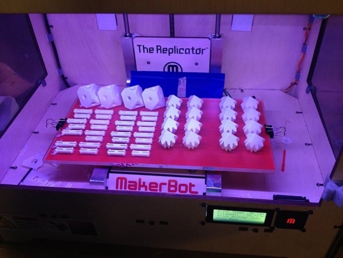
Small Update: I added a picture of the 8 rows of ditto capabilities (I was still testing the hairspray method, so one part came off) I don't think the LED on top is a good idea any more. It flickers too much and has become annoying. This is a replacement build platform for your Makerbot Replicator (single or dual). It takes advantage of the extra space along the x axis that is not currently used. If you have taken advantage of the Sailfish firmware upgrade, you can use the ditto functionality to get two more columns of parts on one build plate. If you just want to use single extrusion, this will let you build 33mm wider with either the right, or left extruder. The extra surface area of the build plate will take longer to heat up, so you should only do this modification if you want the extra room, or if most of your prints are multi-hour affairs. Here is the saga that led up to my larger HBP: My original aluminum HBP was slightly warped from the start. I haven't been too bothered by it until I started printing with PLA. The plate is slightly dished when cool, and domed when hot. I can't print on the corners with ABS, but I can't print at all when the plate is cool. I decided to switch to a glass build plate. I got two borosilicate plates 12x6x1/4 from McMaster Carr. (I should have probably gotten the 3/16, but I couldn't resist the 1/4" for the same price.) I found that the heat wouldn't even think about creeping out to the "wings" through the glass. It only conducts the heat straight up. I took some thermal images from the original plate, and the smaller glass. See the PDFs for comments on my findings. I decided to use information from Gary's update http://www.thingiverse.com/thing:43207 and some of my own electrical experience to make my own plate. It has 2 zones of trace with the outer zone packed more closely together and the inner zone spaced apart. There are no screw holes, because the screws are attached to trace left on the bottom. Here are the specs for each zone: Both zones are .75 mm wide on 1oz, copper double sided PCB paralleled together so each receives 24VDC. Center zone is 259 cm area, 11,484mm long trace, 7.44 Ohms, drawing 3.23 Amps for a total wattage of 77.62. Watts per sq.cm is 0.30. Outside zone is 200 cm area, 13,268mm long trace, 8.59 Ohms, drawing 2.79 Amps for a total wattage of 66.87. Watts per sq.cm is 0.33 - 10% more than the center. I cut the new design on the engraver at work after hours. I was shooting for a parallel resistance of 4 Ohms so I would draw a similar 6 Amps as the original. Hit it on the first try! The new plate takes longer to reach temperature because it has more surface area, and the thick glass I got. The original and the 3/16 glass on the original HBP board took about 8 minutes. The new one took 16 minutes or so. It is in my unheated garage, and I had my sides off, so it probably won't take that long with it all buttoned up. The glass holds the heat between prints more than the aluminum plate did. I plan on swapping out the plates when I am making lots of parts. I will find a way to store the spare plate near the top of the hood, so it is warmed up for the next go. Let me know what you think, or if you have any questions. I haven't made files for PCBs before, so if you need something else, let me know in the comments. Instructions When I took my old board off, I noticed the LED wasn't working. The original connector from MBI was wired reversed polarity for the heat. The LED is dead! The new High brightness LED is on the top surface of the tab, pointing into the edge of the glass. It lights the glass beautifully, and I can write on the bottom surface for glowing lettering or logos while building! Here is the place I got information on resistance of copper PCB: http://circuitcalculator.com/wordpress/2006/01/24/trace-resistance-calculator/ I am working on a system to clip the glass down. I left all the copper on the bottom, so I could solder on parts around the edge. The new platform is 37mm wider on both sides than the original. So far, I have printed ditto with a sliced model for the right extruder with these settings: Far left column of objects placed at the far left of the normal area. Far right column of objects placed 33mm over the edge of the normal area. Turn on ditto printing, and get 2 more columns worth of objects on the new platform. I have also sliced and printed single extruder models that are up to 33mm longer than possible before. You need to be careful to set them up in the right spot: Models printed with the right extruder hang off on the right side, left extruder models hang off on the left. Making the board: Use the top and bottom PDF marked "trace" to etch the 1oz. board (the black lines are where copper should remain), or use the PDF marked "cut" to mill a .75mm wide gap between the remaining copper traces (the lines are center of the tool path). Test the resistance of the trace. It should be about 4 Ohms. Put the components onto the board, and wire it up with a remote connection, or solder the existing wires directly onto the board to prevent connector failure. Components: 4.7K resistor goes between the signal and 5V (white and blue on mine) 1.0K resistor series with a high brightness white LED between the +24V and Heat - (I made mine wrap around the tab and point into the edge of the glass platform to light it up!) 0.1Uf capacitor between the gnd and sig near the tab 100K surface mount thermistor at the center of the plate between gnd and sig.
With this file you will be able to print XL Heated Glass Build Platform PCB 300mm x 150mm with your 3D printer. Click on the button and save the file on your computer to work, edit or customize your design. You can also find more 3D designs for printers on XL Heated Glass Build Platform PCB 300mm x 150mm.