XRAD'S REAL LASER BLASTER WITH LIDAR SCANNER
thingiverse
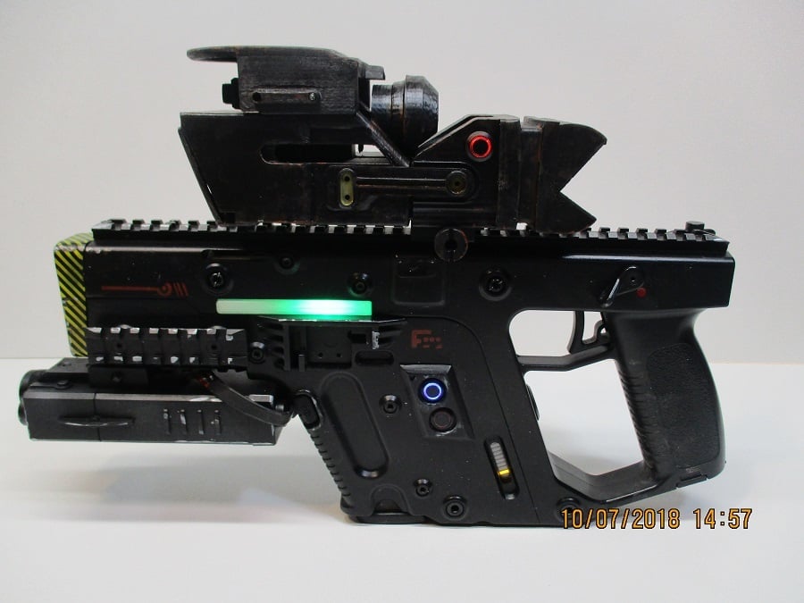
This thing is the LIDAR ( IRDAR ) scanner build (Maybe a laser blaster thing some day, see below). It is a real IR distance sensor connected to a Teensy 3.2. It displays real time information on a 1.8" Adafruit TFT. Scan angle from 60-120 degrees using servo.h lib. Also, Adafruit FXMini used for 8 sounds pin triggered. Start-up, default hum, and sounds for each distance 0-6m away (6 increments). It will fit any picatinny rail. I just happen to have it on my laser blaster. Last pic above is LIDAR shooting into corner 5-7m away! Pretty cool! Initial bit of code was from an ultrasonic sensor but the distance (40cm max) was not useful. So I converted the code to use a TFMini which has a 14m range. Really only 10m is useful so I adjusted display code to show max 10m range. Outside of ~6m, if there no reflecting object , the default hum will play. Inside ~6m , there are the 6 warning beeps, each increments in tempo and pitch. You can get some of the needed code from TFMini retailer/website/github. I then added a bunch of code for sound, changed the scan mode, added a cool start up display, and display will show a white dot when object is 'dangerously' close , less than r2 (r2 = r_beam * .33 or ~ 3.3m), and a red dot when between r2 and 10m. Pin selection #defined for the Teensy 3.2 making wiring a breeze (see below for link to code). This setup also requires sound files which I created on Audacity using mixed mono tracks at 16000Hz wav so that FXMini can play them quickly. Had to use 3904 transistors to get the most out of the loop/hold /play features of the FXMini, as serial control was not easily implemented for 8 tracks. See adafruit FX tutorial for more detail. The switch mode is super easy to use which is why I like these adafruit wav boards. I don't have a way to upload the wav files to this site so you can listen to them on youtube and make your own. See youtube link. https://learn.adafruit.com/adafruit-audio-fx-sound-board/overview The 3D parts designed to mount to a RIS PEQ Box (like this but without battery: https://www.airrattle.com/PEQ-Box-w-Small-Connector-10-8V-1100mAh-Battery-p/jgm-110.htm ) . One end of the box is trimmed off just enough to make the box an open 'tunnel' to fit all the electronics. The other end is a removable cover which is removed and not used. And then all the bumps are smoothed off the box so the two chassis pieces slide on. Basic Parts List: Teensy 3.2 (3.3v logic!) This is a reliable durable board w/fast processor TFMini (3.3v logic!) adafruit FXMini Pololu Mini Pushbutton Power Switch with Reverse Voltage Protection, LV Pololu 5V, 5A Step-Down Voltage Regulator D24V50F5 Adafruit 1.8TFT led momentary pushbutton switch angel eye 12mm Black case, any color LED u like 1 x 300 ohm resistor (for the angel eye) 8 x 500 ohm resistors (go between the Teensy pinouts and the 3904's base) 8 x 2n3904 transistors (grounds FXMini 8 wavs when triggered by the Teensy via 3904s ) Standard sized servo (I had good luck with Futaba S3004, some other brands scanned in reverse, the display scan lines and the servo.write are linked so you would have to add reversing code at servo.write( i );) Speaker: CE32A-4 Adafruit 2.5 watt class D amp FLOUREON 2S 7.4V 800mAh 25C JST Lipo bunch of tiny allen head wood screws and the usual solder, wire, tools etc..... NOTES to read: the battery cover is a close fit, but needs a base extension and method to temporarily fix to battery box. This is a prototype. Most everything fits well, but consider it a kit. You will also have to add a very thin piece of plastic (a cover) to the scan head chassis right under the TFMini mount to hide the servo. I use Devcon two part plastic welder (Ace hardware). Works great on ABS. Speaker fits into rear of Scan head chassis. There is a speaker cover ring that has to be trimmed w/angle cut to fit. Standard servo fits w/minimal fitting into servo slot, and front servo mount screws into scan head chassis capturing the servo. Servo then held in place w/four screws. The TFMini mounts to front of the servo mount with 2 screws. Note that the TFMini mount sits beneath the actual Futaba servo arm mount, which is screwed to top of the TFMini mount. this gives better clearance for the wires. You will have to clean up the TFMini servo mount hole. The TFMini is a somewhat fragile unit. 3.3v logic and 5v power like the Teensy 3.2!!! Don't drop the TFMini. Wiring is not challenging, just a tight fit. See some of my vids and pics for basic wiring. DO NOT run the servo off any of the Teensy or the FXMini 3.3 or 5v pins. Run battery power to the voltage regulator first, then to the low voltage pololu switch (which is triggered by momentary angle eye switch) , then run power to all boards, servo, TFMini , etc, and make sure all grounds are connected to common ground. and then back to pololu switch. The pololu lv switch can handle more than the required amps. See pic above for some basic wiring. Make sure you can fit the battery in front of the servo before gluing the battery box in place. Wiring, and battery connectors, 5v regulator, and 2watt amp fit on each side of servo. Teensy, 3904's, FXMini go inside the PEQ. Make sure you can reach the micro usb ports on the FXMini and the Teensy in case you want to update them. Also, insulate/isolate the boards. I wrapped them in electrical tape. Also, I hot glued the TFT to the back of the TFT mount, and then glued TFT mount , TFT guard, chassis together with Devcon plastic weld. Make sure to solder on the TFT wires first. There is a cut out in the TFT mount for extra LEDs if u want to add. This whole unit then slides over the PEQ from the pic rail lock end, and the scan head chassis slides over the PEQ from the other end (Or you could make your own pic rail mount system and box) Side rails hold the unit together(make a mirror image copy to have x2 pieces), but I found that it was too tight w/electronic wiring to risk screwing together on the prototype. You can use less wire and use shorter screws on the side brackets if you are careful. REMEMBER: You may have to change orientation and lay flat and/or use supports to make best 3D print. Regarding the Real Laser Blaster: It has a Plasma Core power source internally run by a trinket in a fully removable self powered clip. The blaster itself has relatively few 3D parts. Mostly, it was machining of aluminum parts for internal function. Uses 2 wide beam green lasers. You can see it here: https://www.youtube.com/watch?v=HWKC-wcrbZE&t=3s Of course there is always a better way to do the code, but here is what I came up with. You can find the code here: https://forums.adafruit.com/viewtopic.php?f=25&t=142445&p=710141#p710141 or here: https://www.rctankwarfare.co.uk/forums/viewtopic.php?f=44&t=25611&p=249910#p249910 If you can't see the code, you may have to join. It's free ,and a great website! Here is LIDAR Thing in action: https://www.youtube.com/watch?v=OzD6tEk0OKQ Sounds and Display (I need to make the start-up about 1.5 sec longer to match the pulse effect). Also, too close for default hum effect...: https://www.youtube.com/watch?v=ngPoOk9I8WY&feature=youtu.be
With this file you will be able to print XRAD'S REAL LASER BLASTER WITH LIDAR SCANNER with your 3D printer. Click on the button and save the file on your computer to work, edit or customize your design. You can also find more 3D designs for printers on XRAD'S REAL LASER BLASTER WITH LIDAR SCANNER.