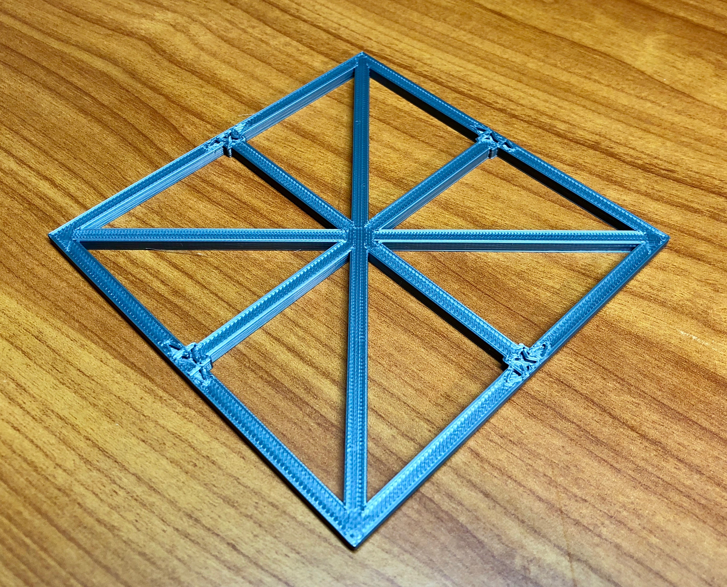
XY Calibration Square - 100mm
prusaprinters
<p><strong>Calibrating X and Y axis on the Original Prusa i3 MK2, MK2.5 and MK3</strong></p> <p><strong> UPDATE 26 October 2018</strong> Modified step 11 to show the option to save changed values to firmware using M500 command.</p> <p><strong> UPDATE 6 October 2018</strong> Confirmed this process continues to work for the Prusa MK2.5 and Prusa MK3 printers. This process also works well for most other printers that use Marlin firmware.</p> <p><strong> UPDATE 5 April 2017</strong> Changed reference from M501 to M503. Note that Prusa Research i3 MK2 firmware 3.0.10 allows you to save the PID settings directly. I have not yet tested that firmware, so will leave the instructions as they exist. This method still works for newer and older firmware.</p> <p><strong> UPDATE 25 January 2017</strong> Calibration Square now has labels and an additional cross beam. Thanks to Jonas Hansen for helping me to create the initial version, and thanks to Kyle Wiehe for the updated version.</p> <p>There are four axis' that can be calibrated on MK2, X (left to right), Y (front to back), Z (height) and E (extruder). I found my printer was printing pieces that were noticeably undersized, especially on the Y axis. Using the process recommended in the Instructables article linked below, I was able to quickly improve calibration in the X and Y axis.</p> <p>Follow the steps below to calibration your X and Y axis:<br/> 1.Connect to your printer via a USB connection (direct to computer or Octoprint, etc.)</p> <ol> <li>Issue the M503 command</li> <li>Scroll back through the output of the M503 command and look for the M92 output. Mine was M92:X100.00 Y100.00 Z400.00 E161.30. Copy down these numbers. The M92 command sets the numbers of steps the stepper motors will move based on movement instructions in your GCODE</li> <li>Download, slice, and print the calibration square included with this Thing</li> <li>Before removing the square from the bed, note that the X-axis is left to right movement and Y axis is front to rear movement.</li> <li>Using calipers, measure the distance across the X-axis in at least three places. I suggest measuring 10mm from each end, plus once in the middle. Write down these distances. </li> <li>Average the three distances. Write down this average for the X-axis. Mine was 99.79.</li> <li>Using calipers, measure the distance across the Y-axis in at least three places. I suggest measuring 10mm from each end, plus once in the middle. Write down these distances. </li> <li>Average the three distances. Write down this average for the Y-axis. Mine was 99.63.</li> <li>Next, use this formula to determine new M92 values:<br/> New M92 value = Desired movement / Actual movement<em> Current M92 value<strong>So for example,**</strong>New M92 for X (100.21) = 100/99.79</em>100<strong><strong>So for example,</strong></strong>New M92 for Y (100.37) = 100/99.63*100**</li> <li>Create the new M92 command by replacing the X and Y values above with the new calculated values:<br/> M92 X100.21 Y100.37 Z400.00 E161.30</li> <li>This changed code can be activated in two ways. The easiest is to enter the new command while connected to the printer via USB from your computer, then enter M500 to save the value. You can confirm the new value was stored by entering M503 and looking for the updated M92 line in the config. The other option is to change this line of code in the startup GCODE in your slicer profiles. To do this, place this line in the Startup GCODE in your slicer. In Simplify3D this is placed in the Scripts --> Starting Scrip area. In Slic3r this is in Printer Settings --> Custom G-code.</li> <li>Re-slice the Calibration square</li> <li>Re-print the Calibration square</li> <li>Mark and measure the new calibration square as in steps 5-8 above</li> <li>Average the distances for X and Y These should now be closer to 100.0mm</li> <li><p>If you are satisfied with the results, you are done! If the distances are not as close to 100mm as you desire, if not happy with results, repeat the calibration process.<br/> Note that this test was done with PLA. When you change material, you should re-test dimensions, and may need to re-calibrate your M92 values.</p> <p>If you want to adjust your Z or E axis, please refer to the Instructables article.</p> <p><a href="http://www.instructables.com/id/Calibrating-your-3D-printer-using-minimal-filament/">http://www.instructables.com/id/Calibrating-your-3D-printer-using-minimal-filament/</a></p> </li> </ol> <h3>Print instructions</h3><h3>Licence: Creative Commons - Attribution Category: 3D Printing Tests Print Settings</h3> <p><strong>Printer Brand:</strong> Prusa</p> <p><strong>Printer:</strong> [Prusa Mk2]</p> <p><strong>Rafts:</strong> No</p> <p><strong>Supports:</strong> No</p> <p><strong>Resolution:</strong> 0.20mm</p> <p><strong>Infill:</strong> 20%</p> <p><strong>Notes:</strong></p> <p>Printed on Original Prusa i3 MK2, as well as MK2.5 and MK3</p>
With this file you will be able to print XY Calibration Square - 100mm with your 3D printer. Click on the button and save the file on your computer to work, edit or customize your design. You can also find more 3D designs for printers on XY Calibration Square - 100mm.