Y.A.R.M.A.U.S. V2 (Arcade Spinner Controller)
thingiverse
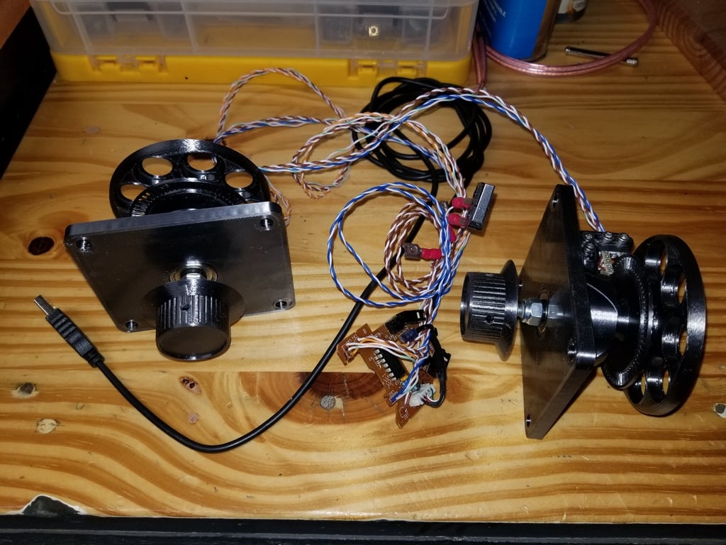
This is an enhanced rendition of my initial 'Y.A.R.M.A.U.S.' spinner design, which can be found here: https://www.thingiverse.com/thing:4354590 **Standard Y.A.R.M.A.U.S. Features (V1 & V2)** - Fits a standard Happ joystick drill pattern - Dual 608 skateboard bearings (smooth and heavy duty) - Adjustable sensor PCB mount - Adjustable flywheel inertia (match the feel of the dials from your favorite games) - 1/4-20 hardware (so we can support our local hardware stores!) **Y.A.R.M.A.U.S. V2 Improvements** - Lower profile (fits slimmer controller enclosures) - Larger diameter code wheel (higher PPR possible) - Simpler and stronger sensor PCB mount - Adjustable flywheel inertia (match the feel of the dials from your favorite games) To assemble everything, follow these steps: 1. Attach the 608 skateboard bearings to the spinner body. 2. Install the adjustable sensor PCB mount onto the spinner body. 3. Attach the code wheel to the spinner shaft. 4. Add weights symmetrically to keep it balanced. **Knob** I remixed the Tempest knob from here to fit a 1/4-20 shaft and M3 grub screws: https://www.thingiverse.com/thing:3626107 To attach the knob, follow these steps: 1. Attach the knob to the spinner shaft using M3 grub screws. 2. Use a 1/4-20 tap to clean out any debris from the threading. **Flywheel** The 8 holes in the flywheel are sized to fit up to 3 US pennies each; add as many pennies as required to get the feel you are after.
With this file you will be able to print Y.A.R.M.A.U.S. V2 (Arcade Spinner Controller) with your 3D printer. Click on the button and save the file on your computer to work, edit or customize your design. You can also find more 3D designs for printers on Y.A.R.M.A.U.S. V2 (Arcade Spinner Controller).