Y Axis Linear Rail and Belt System
prusaprinters
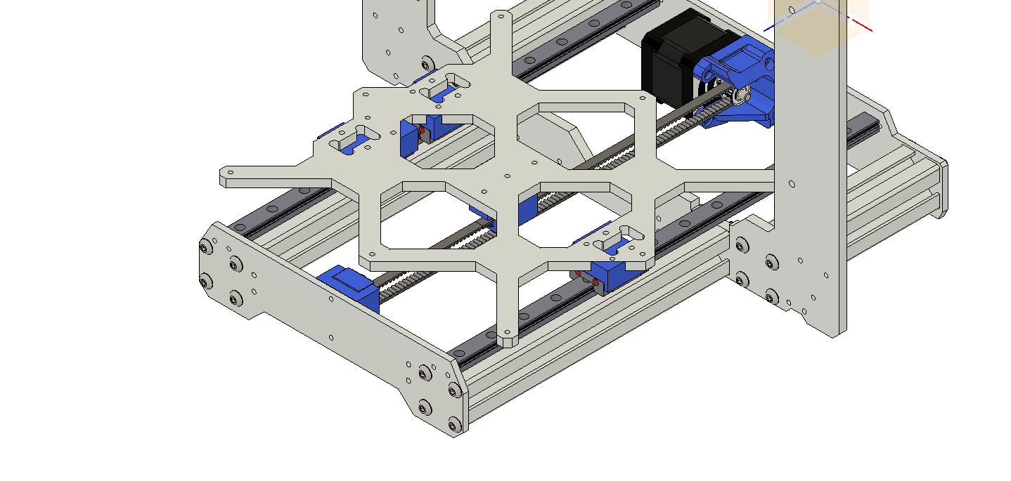
<p>After running my machine for about a week with this system <a href="https://www.prusaprinters.org/prints/20284-y-axis-linear-rail-remix">https://www.prusaprinters.org/prints/20284-y-axis-linear-rail-remix</a>. I was not completely satisfied as I really wanted the rails to be mounted directly to the frame extrusions. It took some minor modification of the Frame and the Frog and I am very happy with the results, it is much quieter than the previous version and print quality has improved. I also made some changes to the Y belt system, improved the motor mount with 4 mounting screw and calibration stop. Modified the belt holder from a stock MK3 so that when it hit's the calibration point the 4th mounting bolt will clear the holder and added a 4mmx3mm hole on the mounting side to make locating the center hole of the heatbed easier. The Y tensioner remains unchanged from my previous version. <a href="https://www.prusaprinters.org/prints/20317-y-axis-belt-tension-system-mk3-mk3s">https://www.prusaprinters.org/prints/20317-y-axis-belt-tension-system-mk3-mk3s</a></p> <p>The rails are locked down to the front extrusions with 2 M3 T-nuts and M3 12mm Socket Head bolts. The front and rear guides should be printed for installation but after calibration is complete they can be removed</p> <p>Instructions. (After you print all the parts, including the jigs - step 2) For details on general disassembly and assembly please refer to the installation instructions for your printer. This is easier to set up if you remove the Y axis belt system first.</p> <ol> <li>Modify the frame as shown in the pictures so that the 45 degree angle of the frame is at 90 degrees to the front extrusions and spans the length of the extrusion (30mm) also make sure the top of the extrusion is at least .01mm taller than the frame so that the rail only contacts the extrusions. I used a coarse square file to modify the frame. Make sure that all the dust and metal filings are completely removed from the printer prior to proceeding. STL of the modified frame is included for reference.</li> <li>Modify the frog by adding additional mounting holes so that the carriages can mount securely to the frog. Jigs are in the temp parts 3mf file. Mount each jig with m3 screws/nuts. Use a 3mm drill bit for the additional holes (drill press is suggested). STL of the modified Frog is included for reference.</li> <li>Discard the jigs and install the carriage mounts to the frog without inserting any screws, the mounts should snap into place</li> <li>Install the front and rear rail guides (6 total). </li> <li>Prepare the 330mm MGN12 rails. The left rail will have an MGN12H and MGN12C and the right rail will have a single MGN12C.</li> <li>Insert the rails with the cartridges into the guides with two M3 T-nuts with M3 12mm Socket Head bolts on each side. Any two holes should work but I choose the holes that were the farthest span available along the front extrusion for more linear stability. </li> <li>Tighten each screw in the system (mounts, guides rails) until it is almost tight then loosen it 1 turn.</li> <li>Starting with the carriage mounts on the frog slowly tighten each screw in a cross pattern such as top right, bottom left, bottom right, Top Left. Every time you tighten up a screw test that the rails are perfectly smooth. Once the carriages are tight and run smoothly on the rails start tightening the rail guides following the same process as before, go slow, cross pattern, check movement after each adjustment. Last tighten the rails to the extrusion, same process, go slow, cross pattern, check movement after each adjustment. This step took me about 20 min.</li> <li>Install the belt system with tensioner, belt mount and motor holder. It's important to change out the belt system (at least the motor mount and belt holder to insure correct calibration. There is an STL file for the race for the idler to align it on the Rod</li> <li>Calibrate the printer and have fun! After calibration is complete the front and rear rail guides are no longer necessary and can be removed. </li> </ol> <p>Shopping list in addition to re-used parts.<br/> Rails...<br/> 2x MGN12 330mm Rail<br/> 2x MGN12C Cartridge<br/> 1x MGN12H Cartridge<br/> 22x M3 12mm Socket Head bolt (6 are used for the guides)<br/> 10x M3 3030 T Nut (6 are used for the guides)</p> <p>Y Belt System<br/> 1 GT2 20T 5mm Toothless Idler<br/> 1 5mm 24mm smooth steel rod (or print one, file is included)<br/> 2x M3 13mm coupling nut<br/> 5x M3 10mm Socket Head Bolt (pack of 10) You need 5.<br/> 2x M3 14mm Socket Head Bolt you need 2<br/> 2x M3 20mm Socket Head Bolt</p> <p>If people like this mod I will make up a hardware kit for it as some of the parts for the belt system are not easy to find in small quantities. and sometimes the 330mm rails are not readily available.</p> <h3>Print instructions</h3><p>The rail system was printed on 0.2 quality for all the guides, the carriage mounts at 50% infill. Belt system 0.2 25% infill, the race and the rod were printed at 100% .3 YMMV</p>
With this file you will be able to print Y Axis Linear Rail and Belt System with your 3D printer. Click on the button and save the file on your computer to work, edit or customize your design. You can also find more 3D designs for printers on Y Axis Linear Rail and Belt System.