Y-Carriage supported Linear rail upgrade for Geeetech printers
thingiverse
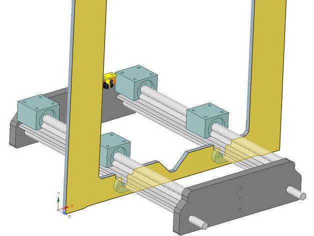
If you're reading this, it's probably because (like me) you're tired of constantly re-adjusting the bed height due to the 8mm smooth rods that flex easily. To make matters worse, my printer's rods had a slight bend. So, I'm upgrading the Y-Carriage 8mm smooth rods on GeeeTech printers (and possibly others) with 12mm supported linear rails. The re-designed y-carriage end supports are a direct replacement for the existing aluminum supports. The rear support also incorporates a built-in mount for an optical endstop sensor. You will need: * 2 x SBR12-420mm Supported Linear Rails * 4 x SBR12UU Bearing Blocks * 1 x Optical Endstop Sensor * 2 x M3 Nuts and M3 x 10mm Bolts (To Mount Optical Sensor) * 16 x M5 Washers and M5 x 10mm Bolts (To Mount Aluminum Bed) All parts are available on eBay. Instructions: Unless you have access to another printer, I suggest you print the front & rear end carriage supports, drilling template, and endstop blade before dismantling your printer. Remove the existing front & rear Y-Carriage End Supports and y-axis smooth rods. Cut 2 slots into the X-Z aluminum frame for the linear rails to sit in. (See photos and drawings for details). Re-assemble your printer using the new Y-carriage end supports and linear rails. (Don't forget to slide on the bearing blocks first). The mounting holes for the new bearings are spaced further apart. So, you'll need to drill new mounting holes. Attach the drilling template to the aluminum bed using one of the old bearings. Mark and drill the location of the new holes. - Note...Due to their size and position, the new holes will overlap by a few mm. Install and connect the optical endstop. Unlike micro-switches, optical sensors require a 3rd wire to supply 5 volts. If your printer uses the Sanguinololu board, you'll need to bridge out a link on the underside of the board. This connects the middle pin of the endstop connectors to the Sanguinololu 5v supply. Attach the endstop blade to the underside of the aluminum bed. Note...The blade position shown in the drawings are indicative only. I recommend that you accurately position and mark your bed before drilling. Ensure you allow enough room for the bed to stop before the linear bearing hits the rear carriage support. Re-attach y-axis stepper motor, tension pulley, and drive belt Repositioning the Origin The longer Y-Axis travel means the bed position relative to the extruder will shift when the bed is homed to the limit switches. This means when the extruder moves to the origin (ie G1 X0 Y0), the nozzle won't position over the front/left corner of the bed. To compensate for this, set the travel limits in configuration.h as follows: // Travel limits after homing #define X_MAX_POS 210 #define X_MIN_POS -10 #define Y_MAX_POS 210 #define Y_MIN_POS -35 Print Settings Printer: GeeeTech Prusa I3 Rafts: Doesn't Matter Supports: No Resolution: 0.2mm Infill: 30% Notes: For added strength, I recommend printing the carriage end supports in ABS
With this file you will be able to print Y-Carriage supported Linear rail upgrade for Geeetech printers with your 3D printer. Click on the button and save the file on your computer to work, edit or customize your design. You can also find more 3D designs for printers on Y-Carriage supported Linear rail upgrade for Geeetech printers.