YA Filament Jam Sensor
thingiverse
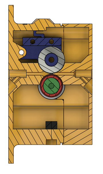
I made this filament jam detector to ensure reliability and ease of use with my printer. It has a few features worthy of note: - TPU tire to grip filament - Printed tensions springs integrated on pressure arm - Easy and precise spring tension adjust (uses screws) - Transparent LED light pipe for visual sensor state feedback - All 688 ball bearing movement - ~0.6mm filament movement resolution - For 1.75mm diameter filaments - No-support printing - Several mounting options In case you are not familiar with what a jam sensor is... Marlin can be configured to use what is basically an optical endstop to determine if filament is flowing as expected per the motion planner. Repeated on/off toggling of the input pin tells Marlin the filament flow is working as expected. If so many mm's of filament has been extruded without seeing a state change, Marlin can pause the print and wait for you to fix the clog or refill the filament if it runs out (potentially saving prints and filament). You can configure the length of filament Marlin will allow to print before pausing. In the case of this jam sensor, this value can be safely set as low as 1mm. This will ensure a good print in nearly most cases when filament jams. The exception being very small layers on parts, which could still end up with missing layers after just 1mm worth of "air printing". ***Thing BOM: 1@ optical endstop: https://www.amazon.com/gp/product/B081W4KMHC/ 3@ 688 size ball bearings 2@ M3-8 3@ M3-16 7@ M3-10 1@ M3 nylock nut 1@ printed lowerBox 1@ printed upperBox 1@ printed shaft 1@ printed armLeft 1@ printed armRight 1@ printed encoder_40T 1@ printed tire (TPU) 1@ printed lightPipe (transparent) Optional: 1@ printed 90DegBracket I designed the sensor mount such that it mounts through the actual sensor holes. So this may work with a lot of other similarly shaped sensors that have different shape PCBs (no guarantees). ***Assembly: Slide the TPU tire on to the shaft, and rotate so the splines engage. It may still rotate when forced by hand; this is OK. Snap the encoder on to the shaft, making sure the splines are oriented correctly and it is fully seated (no wobbling or gap). Slide 2@ 688 bearings on either end of the shaft and set the shaft assembly aside. Slide a 688 bearing on to the right arm. Secure the left arm to the right arm using a pair of short M3 bolts from the left side. Use another short M3 bolt through the right side to secure the bearing to the arm. Install the arm assembly into the mount in the lower housing using an M3 bolt and nylock nut. To aid assembly, an allen wrench or screwdriver can fit through the hole in the right side of the lower housing. Glue the transparent light pipe into the hole in the bottom of the lower housing. Install wiring onto the optical sensor, and secure it inside the lower housing using a pair of M3 bolts (nuts optional). Install the shaft assembly in to the lower housing bearing blocks, oriented such that the encoder wheel is on the left, TPU tire on the right (the wheel should be centered in the sensor). Install a pair of M3 bolts into the pair of holes on the top of the lower housing, and tighten them so the bearing just touches the TPU tire. Attach the upper housing to the lower housing using 4@ M3 bolts. Add PTFE tubing into the inlet and exit holes, and secure with short M3 bolts; do not overtighten, just enough to keep the tubes from slipping out when gently pulled. Verify that filament can easily enter the inlet and exit the outlet tubes, and that it moves through without friction. A slight drag is OK, but if the wheel stops turning you may have to sand down the filament guides and/or drill out the filament paths (the concaved part may rub on the TPU wheel depending on printer tolerances, and 2mm drill works well to clean the smaller areas). ***Firmware: In marlin 2, configuration.h, uncomment the following lines: ``` #define FILAMENT_RUNOUT_SENSOR #define FILAMENT_RUNOUT_DISTANCE_MM 3 #define FILAMENT_MOTION_SENSOR ``` Most pins files don't have a runout pin defined, so you will also likely have to add ``` #define FIL_RUNOUT_PIN whatev_pin_yoboard_uses ``` to the runout section. A runout distance of 3mm seemed like a good balance to me as it gives the extruder a chance to push a minor clog through; you might go down to 1mm if you do a lot of smaller prints. Enjoy!
With this file you will be able to print YA Filament Jam Sensor with your 3D printer. Click on the button and save the file on your computer to work, edit or customize your design. You can also find more 3D designs for printers on YA Filament Jam Sensor.