Z Axis Anti Wobble Nut - ABL version/ Ender 3
thingiverse
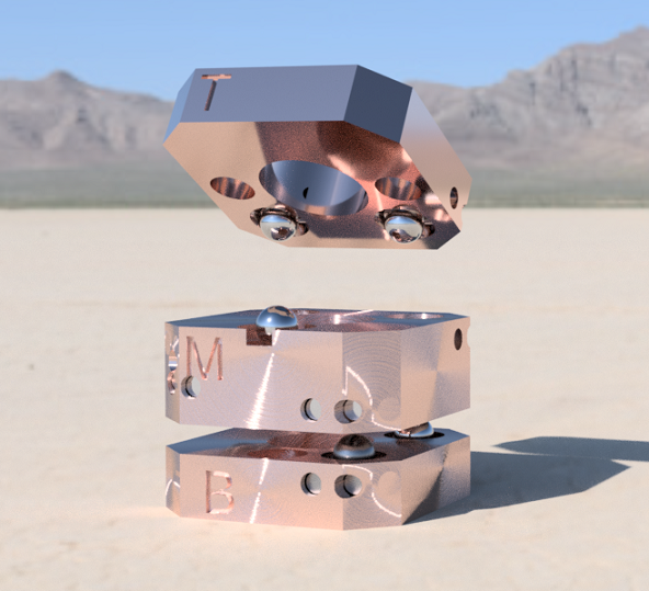
Update: 1/21 complete redesign, new files Successful test, go ahead! PREFACE The problem that the anti wobble nut solves can ALSO be solved (if the top of the lead screw is free) using a z lead screw flexible coupler with a 1/4 in or 7mm ball bearing at the bottom of it to prevent compression. This is a FAR easier option than the anti wobble, that yields nearly identical results. If the top of the lead screw is constrained by a bearing and belt setup (Ender 3 s1), you will benefit from my anti wobble or tekti's on driven sides. This is a remix that solves the wobbly table syndrome caused by 4 unlevel bearings on a plane, present in Tekti's version, just the nature of 3d printing. The wobble caused a z step lost when changing z direction, detrimental if using an auto bed leveling system, but probably unnoticeable if not. Between a 4 legged table with different leg lengths or a 3 legged table with different leg lengths, the latter doesn't wobble while the former does. Idk why, ask Archimedes. This makes for less than 1 lost z step. Parts list: 20 2x8mm needle bearings Search "2x 8mm dowel pin" on ebay 6 4mm ball bearings 11 6x3mm neodymium magnets 2 m3 heat inserts 5mm od 4 shortish m3 bolts 1 long m3 bolt a glass build plate vision miner nano polymer adhesive https://visionminer.com/products/nano-polymer-adhesive?variant=39412520550449 a soldering iron with skinny tip super glue Print on smooth glass, as a bearing will be rolling on the print face. 1. In slicer have top and bottom parts side with 2 holes and flat face down on the bed. NO RAFT!!! Bottom pattern initial layer: CONCENTRIC (IMPORTANT), top/bottom pattern: lines, Infill density: 30%, layer height: .12, line width: .42, supports enabled, overhang angle: 80 deg, support z distance: .13, support x/y distance: .25, support distance priority: x/y overrides z, disable support interface 2. Apply the VM adhesive to the glass build plate, a few drops spread using the brush covering 4" by 4" on the center of the build plate. Spread as thin as possible. 3. Ensure the first layer goes down without any gaps, especially on the top and bottom parts with the flat plane side. If there are gaps on that plane, the bearing won't ride smoothly. 4. Remove supports using small flathead screwdriver, stick through center of support then pry. 5. Fire up soldering iron and heat up heatinserts for insertion into the top part, labeled "T", insert to top of T until approx .5mm below surface. Thread in long m3 bolt to clean out the hole and see if inserts are straight, heat heat insert and apply pressure to bolt to make adjustments. Smooth out ridge created by heat insert. 6. Insert 4 2x8mm needle bearings into top and bottom parts, apply pressure with allen key until they're seated. Print and use "pin_starter.stl" if you're having trouble getting them in. 7. Snip off a dozen or so 1mm chunks of filament. Use soldering iron to "weld" filament chunks into the ends of the needle bearing holes you just pushed in to keep them in place. 8. Insert magnets into top part holes keeping polarity facing the same direction. If unable to force them in with allen key, apply light pressure with soldering iron on, with bigger tip. If they went in without force, apply a drop of superglue to magnet center then push to the edges with a pencil. 9. Insert magnets into bottom part labeled "B" so that they attract the top part with both parts' needle bearing pins facing together. repeat gluing 10. Insert 2 magnets into middle's face holes with ends so that they attract both top and bottom with needle bearings facing together. Do this only on one side. Leave the hole that goes through. Insert pins into side where magnets were applied. Make sure they're parallel and fully seated, use a piece of filament to push in the pins. Stick piece of filament into pin hole, cut slightly after surface and weld shut. Ensure proper polarity and apply 3 magnets to other side, insert pins and weld shut. 11. Check all the pins for parallel. If some aren't, apply light pressure with soldering iron in 5 second increments to make parallel. 12. Set 6 of the 4mm ball bearings on top and bottom pieces, align so that T M and B are all on the same side. 13. Causes of magnet shifting/ un-coupling when moving z are due to an : a. unlevel lead screw nut mounting location, clip a piece of credit card and stick under side with gap in bearing surface. b. X gantry z wheels are too tight, loosen until outer wheels can almost spin freely. c. If you're running dual z, both screws need to be holding weight. Turn the loose side clockwise until you feel it take on weight, but not enough to take weight off the other side. I have a 40-34 motor zip tied to the usually un driven side of x gantry, other weights would suffice. This helps prevent de coupling. 12. Enjoy quality prints.
With this file you will be able to print Z Axis Anti Wobble Nut - ABL version/ Ender 3 with your 3D printer. Click on the button and save the file on your computer to work, edit or customize your design. You can also find more 3D designs for printers on Z Axis Anti Wobble Nut - ABL version/ Ender 3.