Z-axis_linear_rails_MGN12H
thingiverse
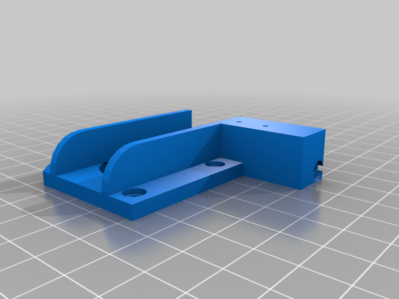
Conversion of the Z-axis with linear rails MGN12H Anet E10 MGN12H; 300mm lg Anet E12 MGN12H; 400mm lg As part of the renovation, I moved the extruder motor upwards so that one Filament change the Z-axis can no longer be accidentally adjusted. For the extruder motor mount above you need a ball bearing 688ZZ (8x16x5mm), which is pressed in. For people who do not want this, I have also provided a solution. Print required components, I printed my parts with 15% support. The X-axis motor mount was printed with 60% infill, the other parts only with 30% infill. The Z-axis conversion can be used with original X-carriages and when converting to MGN12 linear rails, followed by a conversion of the X-axis to beltless. After printing out the required components, the X-carriage must be dismantled. It is best to start with the right side, where there is no motor bracket, as follows, move the Z-axis as high as possible, dismantle the X-axis, dismantle the Z-slide on the right-hand side, dismantle the trapezoidal thread spindle guide at the top right, trapezoidal thread nut as well Place the new component, mount the linear rail with the fixed carriage (!! fix otherwise the balls will fall out of the guide), I have attached the linear rail at the top so that the air gap remains at the bottom, screw the printed Z-axis guide onto the threaded spindle and fix it with 4 screws M3x6mm on the linear rail carriage. Place the X-axis loosely between the Z-axis carriages (1 screw on each side), Carefully lower the Z-axis and only screw the X-axis down at the bottom, so the distance between the Z-spindles is not adjusted much. Move the Z-axis back up and only now screw on the loose threaded spindle guide on top. The same is done on the left-hand side, but before the X-axis is set here, the X-axis motor mount is attached to the stop on the X-axis. If you now push the fastening strap of the motor bracket to the linear rail carriage, the X-axis limit switch is back in its original position. There is an M3 threaded opening on the underside of the X-axis motor bracket, where a M3x20 flat head screw can be used as a stop adjustment. If necessary, extend the cable and tube. Reattach the dismantled components of the X-axis, lower the X-axis and adjust.
With this file you will be able to print Z-axis_linear_rails_MGN12H with your 3D printer. Click on the button and save the file on your computer to work, edit or customize your design. You can also find more 3D designs for printers on Z-axis_linear_rails_MGN12H.