Z-axis Linear Rod and Leadscrew Stabilizer for Geeetech i3 Pro B printer with 8mm acrylic frame
thingiverse
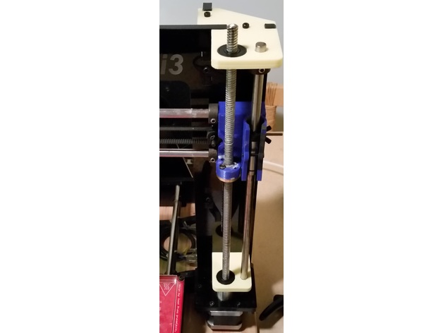
In 2015 I purchased a Geeetech i3 Pro B printer kit with 8mm Acrylic frame. Attempts to use this printer as it was originally designed always resulted in very rough vertical walls due to poor mechanical tolerance with the Z-axis threaded rods. This caused significant problems printing any part which required tight tolerances, such as parts with integrated print-in-place hinges. I tried several 'solutions' which I found here on Thingiverse and on other internet sources, including the common parts which attempt to physically decouple the Z-axis threaded rod from the X-assembly; these helped a bit, but did not solve the root-cause of the problem. The parts you find here (the yellow parts in the photos) are what I finally came up with to truly fix the problem. The XYZ calibration cubes photo above shows the before and after results up-close. Print Settings Printer: Geeetech i3 Pro B printer with 8mm acrylic frame Rafts: No Supports: No Resolution: 0.2mm Infill: 100% Notes: Material type, infill density and resolution is up to your personal preference. Personally, I printed mine using ABS plastic and 100% infill to maximize the part strength and allow me to drill holes in it wherever I want to later. Post-Printing You may want to lightly file all exterior edges when done, for aesthetics and fit. Avoid filing the inside of the printed holes where possible; the fit for the linear rod and 608 bearings should be somewhat tight. How I Designed This I used a digital caliper (accurate to 0.02mm) to measure the top-most acrylic part on my printer, and then re-created that part in Sketchup (not the best tool for modeling solid 3D objects, but I made it work for me) before modifying it to suit my design. First, I made sure to get accurate key measurements for Linear Rod center to Lead Screw center, both of those centers to the printer frame wall, and both of those centers to the upper mourning screw location, before aligning all other part dimensions relative to those core dimensions. Top and bottom pieces share the same measurements for Linear Rod center to Lead Screw center and to the printer frame wall; that's what makes this design work when used in the printer. I also designed these parts such that no layer cooling fan is needed during printing (has no significant overhangs or bridges), and can be printed on a printer where each layer may not be exactly aligned with the previous layer and can be off by as much as 0.8mm in the X and Y directions (such as a printer which is currently is currently experiencing Z-axis wobble). Future plans While this design works very well, I would like to change the lower part to better fit on the existing Acrylic motor mount using its existing assembly screw hole locations instead of (or in addition to) drilling new holes in the acrylic frame. Unfortunately I have not been able to find the original Geeetech i3 Pro B 8mm acrylic frame design files to know the precise part dimensions and hole locations, and I really don't want to spend the time disassembling, measuring, and recreating them as I did with the top pieces. Instructions Parts needed: • These four printed plastic parts. • Four type 608 miniature ball bearings (8mm ID x 22mm OD x 7mm). This bearing size is commonly used in skateboard wheels and should be readily available from any store that sells or services skateboards. • Four M3 grub screws (or regular screws approximately 5mm long, or longer - length is not critical) • Four or more M4 screws. 10-12mm long if threading into the Acrylc frame, or 15mm long if threading into a nut on the other side of the acrylic) Steps to use: 1] Replace the threaded rod with a proper Lead Screw. Personally, I used an inexpensive 8mm diameter 2-start stainless steel Lead Screw with a 2mm pitch and a 4mm lead (a TR8*4-2P Lead Screw). This change required me to reprogram the Z-axis steps per mm setting in the printer's Marlin firmware. 2] Print these four parts I designed, either individually or in pairs using the included files. 3] Remove the X-assembly, Z-axis rods, and Z-axis flexible couplers from the printer, and replace the top acrylic parts with these new printed ones. Also remove the 40mm fan from the lower left side, if you have one installed (it can be re-installed later, using only 2 screws, if needed) 4] insert the 8mm Linear Rod into the 8mm hole in the newly printed top part, and then run it through the 8mm hole in the newly printed bottom part, and finally ensure the Linear Rod goes into the receiving hole in the unchanged acrylic motor mount. This will be used to align your positioning of the newly printed bottom plastic piece, so make sure it is straight and true. 5] Get a cordless drill, and a drill bit which fits loosely into the holes in the newly printed bottom part (these holes are for M4 screws) 6] With the 8mm Linear Rod now in-place as a secured vertical guide from top-to-bottom, carefully postilion the bottom plastic piece so that it is both flush with the acrylic frame and is pressed down against the acrylic motor mount, then use at least two holes of your choice in the bottom plastic piece as guides to drill new holes into the acrylic frame (using the drill and drill bit from step 5) to use as mounting holes for this part. 7] Now tightly secure the bottom plastic piece in-place against the acrylic frame using M4 screws. 8] Remove the 8mm Linear Rod, position/re-mount the X-assembly, and then replace the Linear Rod ensuring it goes through the linear bearings in the X-assembly. 9] Replace the 5mm to 8mm coupler on to the motor shaft, and press a 608 bearing into the large hole on both the bottom and top plastic pieces and gently secure them with a M3 screw (if needed) to stop gravity from pulling the bearing out of the hole. 10] Slide the 8mm Lead Screw through the top 608 bearing, thread it through the Lead Screw nut in the X-assembly, slide it through the lower 608 bearing, and secure it into the coupler on the motor shaft. The 8mm Linear Rod and the 8mm Lead Screw are now secured at both top and bottom in such a way that they will remain parallel with each other, preventing z-axis wobble.
With this file you will be able to print Z-axis Linear Rod and Leadscrew Stabilizer for Geeetech i3 Pro B printer with 8mm acrylic frame with your 3D printer. Click on the button and save the file on your computer to work, edit or customize your design. You can also find more 3D designs for printers on Z-axis Linear Rod and Leadscrew Stabilizer for Geeetech i3 Pro B printer with 8mm acrylic frame.