Z Minimum Height Probe
thingiverse
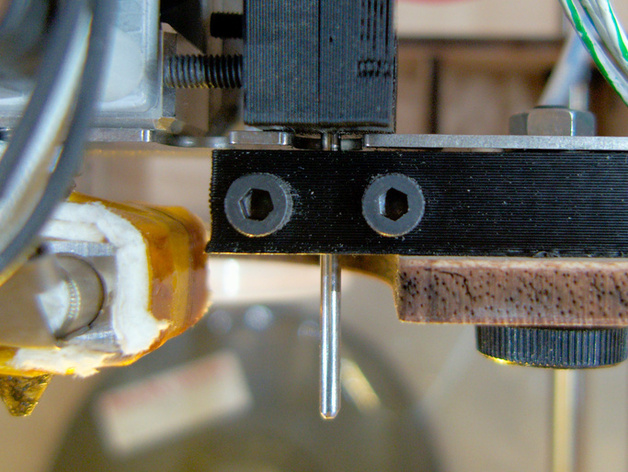
Use this thing to set the Z-Minimum height on a Thing-O-Matic automagically! Instructions This thing has allowed me to dramatically improve the Z-Resolution of my prints. I no longer have squashed first layers (skirts) and the Z height is much closer to ideal. This build has a lot of setup, but once set works remarkably well! This is based on ScribbleJ's auto platform leveling http://www.thingiverse.com/thing:7008. This thing does not automatically level the platform, but does automatically set the Z height. If for some reason your probe or electric connectors fail, this can drive the print head forcefully into your build platform. Use with care! Before you begin, it is a good idea to do the following: Make sure your thermocouple is well insulated to prevent running accidentally running current through it. Ground your extruder head via a wire from the heater support to the PSU body. This will protect your extruder board from a failed heater core dumping +12V through the thermocouple, or if you short your probe to the extruder head. Heat your HBP to around 100C and make sure your HBP is truly level. Parts needed: 4xM3 nuts and bolts 2mm bicycle spoke stranded wire (about 2 meters) 4 wire connector (CD Audio cable) similar to the connectors on the endstops 0.4mm brass or aluminum plate (a beer can would work) 10K ohm resistor heat shrink tubing 3x aligator clips Part 1 - Install and test probe: Print both parts (this is set up for a right hand mount) - the larger part holds the probe; the smaller part makes the electrical connection. Replace the spacer on the right side of the extruder plate with the probe holder. Cut the bike spoke to ~80mm and file one end to a rounded point. Load the spoke into the holder with the point down. Push the spoke down at least 10mm lower than the print head for now and loosely secure it using the M3 nuts and bolts. Attach a ground wire to pin 3 of the connector (black wire in the image). Attach a second wire (+5V) to pin 4 of the connector. Attach this to the Z min connector on the motherboard (red wire in the image). For mounting the probe to the right side of the extruder, thread the +5V wire through the back right hole in the acrylic base. Thread the ground wire through the back left hole. Attach the ground wire to the HBP (I used a solderless lug and attached it via one of the leveling screws) Use aligator clips to temporarily attach the the 10K ohm resistor to the +5V wire and the probe for testing. Scrape a small amount of tape from the HBP and lower the probe so it touches the HBP surface. I used a spot at the center of the right edge, on the Y axis of the HBP. Open ReplicatorG control panel and set the "Jog Mode" to .1mm and attempt to lower the Z axis. If the probe is functioning properly, the Z axis should not lower. Try moving the Z axis up and down checking that the Z axis stops when the probe touches the HBP. After you are satisfied with the functioning of the probe, solder the resistor onto the metal plate. Trim and load the small metal plate into the holder (see the image). This will make the electrical connection between the +5V wire and the probe. Note the larger grove to the right center. This is just the right size for a 1/4watt resistor. Solder the +5V wire to the resistor (don't forget the heat shrink tube!) Thread the holder onto the probe and tighten down. Part 2 - Calibrate probe and set offsets: Scrape any plastic from the print head to make sure it can be lowered all the way to the plate. Heat the HBP to 100C to ensure that it is in the same stat as when you build. Align the probe with the bare spot on the HBP. Loosen the probe and lower the head by hand until it just touches the HBP. Push the probe down gently so it is firmly in contact with the HBP and tighten the bolts. The goal is to have the probe at the same height as the extruder head. If it is higher, the head will be driven into the HBP. If it is lower, it will drag through your prints! Open replicatorg and paste in the following code and run it. Replicator will complain that you are trying to home in the wrong direction. This is normal and expected. You should proceed and follow the instructions. BE READY TO HIT STOP OR TURN OFF THE MACHINE IN THE EVENT YOUR PROBE FAILS! (*** Txoof-O-Matic calibration script ***) (*** Based on Thing-O-Matic Calibration***) (*** Script ***) (*** Created 15 March 2012 ***) (*** ***) (*** This script will guide you through ***) (*** calibrating the start position ***) (*** on your Thing-O-Matic. ***) M18 (This disables the stepper motors.) M01 (Please align the probe with the test area. Once aligned, the HBP will warm upto 110C.) M109 S110 (Set the HBP to 110C) M6 T0 (Wait for the HBP to reach temperature) M01 (Please keep a hand on the stop button or the power supply! If the probe fails, the head will continue to drive into the HBP possibly causing damage. Be ready to stop it!) G161 Z100 (Home to probe area) M18 X Y(Disable motors) M01 (Carefully align the print head to the true center of the HBP) G92 X0 Y0 Z0 A0 B0 (Declare the current position to be (0,0,0,0,0)) G162 Z F500 (Home Z axis maximum; go until reaching the end stop.) G161 X Y F2500 (Home X and Y axis minimum; go until reaching the end stop.) M131 X Y Z A B (record the current coordinates to the motherboard) M18 (disable motors) M00 (Congratulations, your coordinates are now saved! To tweak them, use the 'Motherboard Onboard Preferences' dialog in the Machine menu. Note: You will need to re-generate your gcode files using a new profile in order to use these saved settings.) You may want to save this calibration code to use again later if anything changes to reset your offsets. Part 3 - Configure replicatorg to use calibrate Z offset for every print: NB! The start code is for a TOM with HBP and stepstruder. It can easily be modified to work with any other TOM. Simply use only the "homing" sections. Run the gcode below to determine the proper settings for your Start code: M01 (This will center your HBP and allow you to determine the coordinates of your probe area.) G161 X Y M132 X Y G90 G1 X0 Y0 F2500 M18 Z M01(Lower your Z axis to the center of the platform then open the control panel. Jog the X and Y axis to center your probe in your test area.) Open the control panel and jog the HBP until your probe is over the test area. Record the X and Y values. Open the Start+HBP+Stepstruder.gcode and edit the following lines to match your X and Y values: G1 X28 Y0 F1000 (move the HBP to the probe position) Save the code and test by running it as a build in replicatorg. Keep a hand on the stop button or the power switch incase something fails! Once you are satisfied that this gcode works for your printer, either make a symlink from the machines/thingomatic/ directory to your version, or pop your version into the machines/thingomatic directory. I replaced the start+HBP+Stepstruder.gcode with my auto-homing version to match my TOM w/ HBP. Note that you will need to update this EVERY time you upgrade replicator. Make a test print! Keep your hand on the power switch the first few times until you are satisfied that the homing works properly! NB! ReplicatorG will complain about homing in the wrong direction each time it starts. This is normal. Don't panic!
With this file you will be able to print Z Minimum Height Probe with your 3D printer. Click on the button and save the file on your computer to work, edit or customize your design. You can also find more 3D designs for printers on Z Minimum Height Probe.