Z-Probe for CNC

Z-Probe for CNC

thingiverse

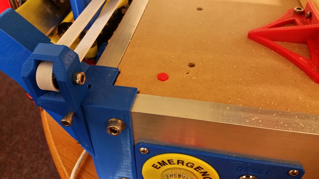
This is a simple Z-Probe for a CNC machine - it lets the machine determine the length of the cutting bit on its own, and essentially self-calibrate the Z-axis, as shown here: https://youtu.be/jmJzWebxJWQ https://youtu.be/w4wR68q8Gww It's designed for a [RS-CNC](https://www.thingiverse.com/thing:3010914), running Repetier Firmware, but should be adaptable to any. It works by mounting a microswitch underneath the bed, under a hole cut through, with a plastic pusher going through the hole. Your bit taps the pusher which pushes the microswitch, which is wired to your Z-probe pin (Z-min on Repetier). The OpenSCAD source is attached - note that it uses [MoreWrong's ScrewsMetric library](https://github.com/More-Wrong/ScrewsMetric), which you can copy down from GitHub. You will need: * A microswitch - we used same ones we'd used for the end-stops, with 10mm mounting hole separation, and standard M2 or M2.5 holes. It's going to do an important job, so make sure it's nice and precise and hasn't been chewed by the dog. * An available Z-min on the your controller board to plug it in. * Some wire and 2-pin inline socket! ### In brief Print bits; drill 8mm hole in baseboard; fit microswitch under hole; put pusher into hole; calibrate; start using G30 H0 to probe; open a beer. ### Detailed instructions for implementation. I'm going to assume you're building a standard RS-CNC, with [MakerFR CNC controller shield](https://www.makerfr.com/en/shop/shield-rs-cnc/) on Arduino Mega and running Repetier, but most of this would apply to most other systems. As usual, read it all before you start! 1. Print the 3 parts. These are: * `ProbeBolt` - the cylindrical pusher should be approx same thickness as your bed - this one is 18mm. If your bed is different, just redesign it: in OpenSCAD, it's literally: `cylinder(d=7, h=18);` The height doesn't have to be super precise, as you can tune out any inaccuracy in the firmware. Making it sit flush looks cool. Making it sit 0.25mm below means it won't get in the way if you happen to need that space for milling. It's called "ProbeBolt" because in an earlier prototype, we were using an actual bolt for this part. * `Z-ProbeSwitchMount` - this is the part you bolt the microswitch to and is screwed to the underside of the bed. * `ProbeHoleGuide` - useful guide tool that fits in the baseboard hole and helps you drill precise pilot holes for the mount. Then you throw it away. 2. Wire up the microswitch - we used the NC (normally closed) connections, same as the end-stops, so that in the event of connection failure, it all halts safely. Fit connector on other end of the wire, long enough to reach. 3. Remove arm from the microswitch (otherwise you risk tiny disturbances in pusher position changing the trigger height), and fit the microswitch to the mount as shown in photo. 4. Decide where you want it mounted. We put ours at (0,0), which was simple and extremely convenient for homing and probing. There needs to be enough space for the mount and the microswitch, including wires - and (0,0) is just above the mains subsystem and emergency switch. There's actually plenty of room, but it's worth being mindful, especially if you have other stuff there! 5. Drill an 8mm hole in your baseboard (make the mill do it!). Don't forget to be careful not drill far below the board if you do it at (0,0), because the mains power lives in that corner...! 6. Take out your baseboard, fit the printed Guide part in the new hole and drill little pilot holes for mounting the microswitch. Orientation doesn't matter much, but it's sort of designed to fit a corner, see photos. 7. Screw the Mount onto the baseboard, see photo. We used little self-tappers - just make sure they don't go all the way through the base! 8. Plug the microswitch into the chosen pins on your controller. On the standard RS-CNC, this was the Maker-FR shield on an Arduino Mega, and we plugged it into the Z-min ("Z-") connector. 9. This is a good time to check the electronics. Plug in your USB and PC, and run G-code M119 with the switch pressed/unpressed to make sure the controller can sense it reliably. 10. Reassemble baseboard, pop the pusher cylinder into the hole and make sure it moves smoothly and clicks the switch. If not, clean the hole a little, and maybe reprint the pusher to be slightly narrower. 11. Check your Firmware. In Repetier, we worried about (in configuration.h): * `#define Z_PROBE_ON_HIGH 1` - this was already set correctly for NC connection. * `#define Z_PROBE_PIN 18` - this was also already correctly set. * `#define Z_PROBE_SPEED 2` - this is nice and slow (2mm/s) for testing, but we increased it to 4 when we were confident it all worked. So in the end we didn't have to change anything! There are more settings to configure, once it's all working, see below. 12. Power up the machine, and do a manual test to see whether the probe works: * remove the bit, so you have some slack if it goes wrong; * hook-up the USB and PC; * home the machine (`G28`) - important! You want the head at Z-max and aware of its location. * try a single point Z-probe operation (simply `G30` in Repetier). It should start heading down at 2mm/s. * once the machine is moving, manually press the probe. If the head stops and retracts, then great! If it doesn't, press the emergency stop! and start debugging. *Caution* `G30` in Repetier will probe at current location, and then will move the head back to _previous position_. If you haven't just homed it, then that could be surprising! We routinely home all before probing. * Check the response on your PC: it should report a meaningful Z-value. 13. Another test: home, and try `G30 H0`, then manually press the probe. This command means "my sensor triggers at 0mm off the base". Adding the H height tells Repetier to store the new Z height, bit like `G92`. Try moving the head slowly to Z5 (eg `G0 Z5 F100`), and see it's 5mm above. Try changing the H value (eg `G30 H0.2`) and going to "X10 Y10 Z0" (or somewhere, not on the probe!) until you've found the exact height of the trigger point. You might set `#define Z_PROBE_SWITCHING_DISTANCE 1.0` `#define Z_PROBE_REPETITIONS 5` which makes it take the average a set of 5 probes in quick succession, bouncing up 1mm between probes. 14. Now you know the trigger height, you can trim out the trigger-point height in the Repetier firmware: `#define Z_PROBE_HEIGHT 0.20` declares that when the probe is triggered, you are physically 0.2mm above the bed, so H0 will now be exactly on the bed. 15. Try it with a real bit. We clamped some 18mm pine on the bed, and tried `G30 H0 R-18` (note the minus sign!), which sets the measured zero point to Z=-18, so Z0 is now 18mm above the board, just like if you'd used `G92` to set origin. 16. Open a beer. We've added a button command to Repetier Host on the PC to go: G28 G30 H0 R-18 G0 X200 Y300 F5000 G92 X0 Y0 G0 Z5 F500 which leaves the head at (200, 300) - change that for wherever you want the X,Y origin to be - and at 5mm above the work. Whenever we put new stock in, we edit that button's command to set the right height, and the right location for starting an operation.

Download Model from thingiverse

With this file you will be able to print Z-Probe for CNC with your 3D printer. Click on the button and save the file on your computer to work, edit or customize your design. You can also find more 3D designs for printers on Z-Probe for CNC.