Zero Probe
prusaprinters
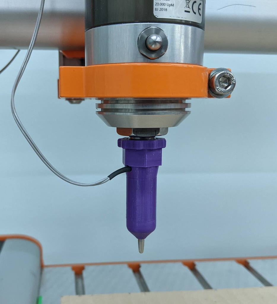
<p>This is a very simple but<em>very</em> sensitive normally closed (NC) touch probe. When the tip is moved by any amount it opens the switch contacts.</p> <p>You should be able to find the parts that aren't printed in your toolbox or spare parts box.</p> <h3>Parts not printed</h3> <blockquote> <p>Screw with a flat (not countersunk) shoulder 3.3mm diameter and a smooth shank longer than 18mm. Mine was from a PC heatsink</p> <p>Washer that fits the screw loosely but has an OD of 9.4mm</p> <p>Coil spring 4mm OD and about 10mm long (extended). Mine came out of a squirt bottle trigger/pump</p> </blockquote> <p>If you don't have these parts it is easy to find similar things to fit, like using a pop-rivet head or a 3.3mm rod and glue a nut to make the head.</p> <p>I have included .stp files so you can adapt the parts you have to work for this design. Failing that, these are very easy to design, even in Tinkercad and its really only the "Guide" that will need to be changed.</p> <p>If you have something very close in size but too big, PLA will easily soften if you warm the metal part up and push it through before it gets too hot and warps everything.</p> <h3>How it works</h3> <p>The probe is attached to the z axis (or fixed to the focus lens in the case of a CO2 laser where the bed moves). When the probe tip touches the bed the screw "sensor" moves up against the spring pressure and no longer touches the washer.</p> <p>Because wires are attached to both the washer and the spring, this movement causes normally closed contacts to open.</p> <p>When the bed moves away from the probe the sensor can move back down and close the switch contact.</p> <p>This action is very accurate and repeatable if the screw shank is a snug fit to the "Guide" hole and the mounting to the laser does not flex.</p> <p>The device is completely passive and the tip does not retract. It does not need power to work, it is simply a switch that opens when the sensor tip touches a surface.</p> <p>It is probably NOT suitable for a 3D printer bed leveling system because it could touch the model you are printing. If you added a removable cap to protrude past the print head then you could use it but there are many available options for bed leveling that don't need this.</p> <p>Update Mar 2022:</p> <p>Added a version that screws directly to an ER11A spindle in place of the compression nut.</p> <p>Also changed the design a bit making the front removable. It uses spring pins in place of the springs and wires. It also shows how to add indicator LEDs. Look at the <a href="https://www.thingiverse.com/thing:5332260">ER11A Zero Probe</a></p> <h3>Print Settings</h3> <p><strong>Printer:</strong></p> <p>Ender 3 v 2</p> <p><strong>Supports:</strong></p> <p>Yes</p> <p><strong>Resolution:</strong></p> <p>.2</p> <p><strong>Infill:</strong></p> <p>20%</p> <p><strong>Filament:</strong> Amz PLA</p> <p>Blue</p> <p><strong>Notes:</strong></p> <p>The Guide part should be printed pointy nose down so that you get a nice even surface for the washer to sit on. Use concentric supports, they are excellent for circular parts.</p> <p>A "Brim" of about 5mm may be necessary if your adhesions isn't good.</p> <p>The cap and sleeve parts are printed with the cavity up (upside down) so supports are minimal, again, use concentric support, it is really easy to remove and leaves very little behind.</p> <p>Preview the sleeve before printing to ensure there is no support material in the internal wire guide hole. The angle is almost vertical so there shouldn't be any.</p> <p>ER11A shell should be printed with no supports, just a brim, with the treaded section up. It will print OK but needs some cleanup internally. This is needed to give a clean line between the cap and shell and so that the final alignment is correct when you screw it down.</p> <p>ER11A cap is printed with the bigger threaded section on the bed, supports can be used.</p> <p>Print time is less than 30 minutes for each part</p> <h3>Post-Printing</h3> <p><strong>Assembly</strong></p> <p>You will need a thin wire for the spring and washer, smaller than 24G depending on how small your printer made the hole for the washer wire.</p> <p>Glue the washer in with epoxy to CA glue after soldering the wire and sanding the downward facing surface flat. This will make sure that the washer seats horizontally and meets the screw shoulder squarely.</p> <p><strong>Soldering wires</strong></p> <p>I used a brass washer so soldering was no problem, I did make a small notch in the outer edge for the wire. You can just as easily cut the rim in the guide if the wire protrudes.</p> <p>*<strong>Tricky part</strong>*. For soldering steel you really need some flux or soldering fluid. I made about 5ml of zinc chloride by dissolving zinc in some hydrochloric (muratic) acid until the zinc was no longer reacting but the acid on its own will also clean the steel and allow the solder to adhere properly. I soldered the spring to the screw the same way. Some plumbers flux may work if you sand the surface of the steel spring and screw otherwise you can try soldering iron tip tinning/cleaning flux (which is usually zinc chloride and ammonium chloride or something equivalent anyway)</p> <p>If you use some of those dangerous corrosive chemicals (using gloves, eye protection etc) then clean the parts afterwards or it may corrode over time.</p> <p>If you get glue on the top surface of the washer it will not make good contact. Sand the top surface of the washer and the bottom surface of the screw before you finally assemble them. This way you will always have good electrical contact and a reliable switch.</p> <p>Printed parts fit together OK, the front 2 pieces were tight but did fit. The top cap is looser and will need to be glued. This part is the best part to modify for a longer piece or one with a clamp to hold it to your lens tube. You can of course use any tube you like to extend the probe as you requirements prescribe.</p> <p><em>Switch is unreliable?</em> One weak point is the chamfered inner edge between the screw shoulder and shank. It may prevent the screw going down all the way and contacting the washer. The switch won't always close when the tip is released. This is usually caused by glue squeezing out from under the washer. I just twisted a big drill bit in the hole to clear out and interfering material and the switch has been very reliable since then.</p> <p><strong>Mounting to your laser, CNC or 3D printer.</strong> I haven't designed this part for all the possible machines, that will have to be done by you. Look for a similar clamp on Thingiverse, there are many options.</p> <p>ER11A cap gets screwed onto the shell. Screw the cap on first with the wire passing straight through the cap, thread it out the side when it has been screwed down all the way, it lines up correctly when screwed down all the way.</p> <p><strong>Candidate for the plunger</strong></p> <p><strong>Notch the washer</strong></p> <p><strong>Solder wire in the notch</strong></p> <p><strong>Level bottom side by sanding</strong></p> <p><strong>Top side of washer</strong></p> <p><strong>Notch the guide if necessary</strong></p> <p><strong>Glue the washer down</strong></p> <p><strong>Check the fit</strong></p> <p><strong>Solder the spring</strong></p> <p><strong>Solder wire to the spring</strong></p> <p><strong>LED Indicators</strong></p> <p>For all these probes, you may like to add a LED (or 2) to indicate the switch state, the Stepcraft electronics seems to have a 1K pullup resistor to 5V on the probe pin, just low enough for a LED to illuminate.</p> <p>If you only use one LED, choose to use the blue or white (or 2 reds etc) in parallel with the switch that indicate the switch is open. It is much easier to see the white LED flash ON than it is to see the red led flash OFF.</p> <p>A red LED in series with the contacts will be on when the contacts are closed but will turn off when the tip touches the bed and contact is broken. A red LED will still signal as a low when the probe contacts are closed (not active) because the voltage drop is across the LED is only about 1.6V. About 3mA will flow through the LED.</p> <p>An white LED in parallel with the switch will light up when the probe tip touches something and will still indicate a high to the software because of its relatively high forward voltage. You could use two green or yellow LEDs in place of the white LED.</p> <p>You can use both or any one of the two above. A circuit that should work is shown below, it uses 2 LEDs, the white will only light up when the probe switch is opened but will still signal a high level signal. The red LED will be ON until the switch opens and will signal a low condition to the CNC.</p> <p>How and where you mount it is up to you, I may add it to the design when I get my autolevel working.</p> Category: Tools
With this file you will be able to print Zero Probe with your 3D printer. Click on the button and save the file on your computer to work, edit or customize your design. You can also find more 3D designs for printers on Zero Probe.