chisel plough diagram 3d models
7684 3d models found related to chisel plough diagram.
prusaprinters
So I added the EasyEDA JSON file, the Gerber-files, circuit diagram and new case STL. If you are interested in a PCB and are located in Europe, please contact me. I have a couple left. Any money I make will go to charity (Paulinchen e.V., an...
prusaprinters
This ensures good contact between the copper pillars and bolts.I continued to solder the remaining components according to the schematic diagram in the previous step.Plugging DS3231 RTC and AMS1117 on the PCB headers.Connecting speaker to PCB control...
cults3d
Connect the wires from the 5V, GND, and GPIO as shown in the diagram above, Also use this to connect the Relay in to the main 12v+ wire of the rest of the printer so it can be shut down from the Octoprint interface. Wire carefully, use good...
prusaprinters
It allows Central Station to select one of the eight contacts, request its state, switch to the next and so on.Overall, the multiplexing chip allows the reduction from 10 wires to 7 (see diagram), allowing us to utilize the 6 wire (plus shielding)...
cults3d
Refer to the included diagram for wiring to the 26 pin header; you will be connecting the thermal camera this way, and the power LED via the 470 ohm resistor. The four connectors marked Flash are for an external flash unit; there is not yet a Thing...
thingiverse
Connect the wires as shown in the wiring diagram: | Arduino | Stepper Driver | Stepper Motor | | --- | --- | --- | | D11 | EN | | | D12 | DIR | | | D13 | STEP | | | 3V3 | VIO | | | 5V | VM | | | GND | GND near VM | | | | M2B | Dark Yellow | | | M2A |...
thingiverse
The connection diagram is in the pictures above. If the toggle switch on the power box is off then the "auto power off" system is completely inactive and your printer would work normally (no risk for auto-off). If you turn the power box toggle...
prusaprinters
Fire retardant filament is NOT necessaryALL Parts are printed without any supports!Perimeters: 4, solid layers: 5 for both top and bottom, Infill: 40%All STL's already have correct orientation for print, just import in the slicer of...
prusaprinters
I included all the plate files here, and also a screencap of the settings i used in case you want to replicate and/or tweak for yourself. https://mechanicalkeyboards.com/ - the Phantom PCB and various parts Miscellaneous Notes and Observations: Order...
prusaprinters
Others might not fit to the case!)1x 5V / 4A power supply with barrel jack connectorSome 0,25mm² wires in different coloursSome 0,50mm² wires for the LED matrix power wires18x Soldering cable shoes M330x M3x8 screws21x M3 nuts (30 if you want to fix...
prusaprinters
A little drop of oil is recommended to put in the bogies but it should roll fine without it too.AssemblyUsing this very scientific diagram™ glue the “detail” under the body. Batteryboxes marked in yellow, frames in orange and the airtank in blue. The...
thingiverse
The TB6600 wiring diagram I added shows a different controller and I do not know if the pinout is the same on the Octopus, so I recommend using an ohm meter and checking for continuity from the pins on the stepper socket boards to the output jacks...
prusaprinters
(see Wiring diagram)I used headers and jumper wires for my prototype, but you might want to solder the whole thing together, if you're not planning on taking it apart later. Route the wires between the stepper motor and the walls of the...
gambody
Every little fold and scale on his rugged bumpy skin is chiseled with careful attention to make it look as realistic as possible. His eyes are rested below the prominent eyebrow-like ridges that give the monster a frowning expression. The head and...
prusaprinters
Cleaning only possible in hot state of the soldering tip.Weller • WP 65 SetWP 65 - Soldering iron 65 W, 24 V with Power-Response Heating Technology.XNT A - Soldering tip chisel 1,6 x 0,4 mm.WDH 10 - Safety rest with Stop+Go function and dry...
prusaprinters
Cleaning only possible in hot state of the soldering tip.Weller • WP 65 SetWP 65 - Soldering iron 65 W, 24 V with Power-Response Heating Technology.XNT A - Soldering tip chisel 1,6 x 0,4 mm.WDH 10 - Safety rest with Stop+Go function and dry...
prusaprinters
The soldering and electronics is not walked through, but you can see the diagram of how to do this. For the Arduino code click here:<br/> <a...
prusaprinters
(6 pieces I think)If you build it all on your desk before touching a single bolt on your printer, you will see where these parts are working together.I will post up some tinkercad screenshots as a kind of airfix model instruction exploded diagram...
prusaprinters
Consider the following diagram to see how. Assuming a rectangular triangle we can use trigonometric relations to calculate the Lorentz force: With a weight of about 20g and an inclined angle of about 10 degrees we get: Which is pretty much the same...
prusaprinters
Because I am using a 12V power supply i chose one 470 Ohm to position in series with the LEDs Step 3:Here is the electric diagram of how the LEDs and resistor are physically arranged. Step 4:Cut the wires and strip the ends to attach...
cults3d
Electronics: I’ve included a wiring diagram to wire up the Arduino Nano to the DRV8825 stepper motor driver and the driver to the stepper motor. It’s a pretty simple wiring job. Just take your time, making sure you correctly identify all the pins...
thingiverse
Electronics: I’ve included a wiring diagram to wire up the Arduino Nano to the DRV8825 stepper motor driver and the driver to the stepper motor. It’s a pretty simple wiring job. Just take your time, making sure you correctly identify all the pins...
prusaprinters
A wiring diagram is included in the attached images. Step by step assembly instructions will be uploaded shortly. </p><p>GRBL configuration is dependent on the motors and drivers you've purchased. The X axis is your linear axis and the steps...
prusaprinters
You only need a few parts to get started as illustrated in the assembly diagram to get started with your first level. </p><p>Shaft Safety note: While shaft wedges do have their ends blunted, please use care when using...
prusaprinters
Please use this diagram as a reference: If you haven't already, upload the code to the Arduino (detailed in the 'Code' section above). Insert the Adafruit Proto-Screwshield (Wingshield) into the Arduino Uno. Remove the female pin header connector...
thingiverse
Please use this diagram as a reference: 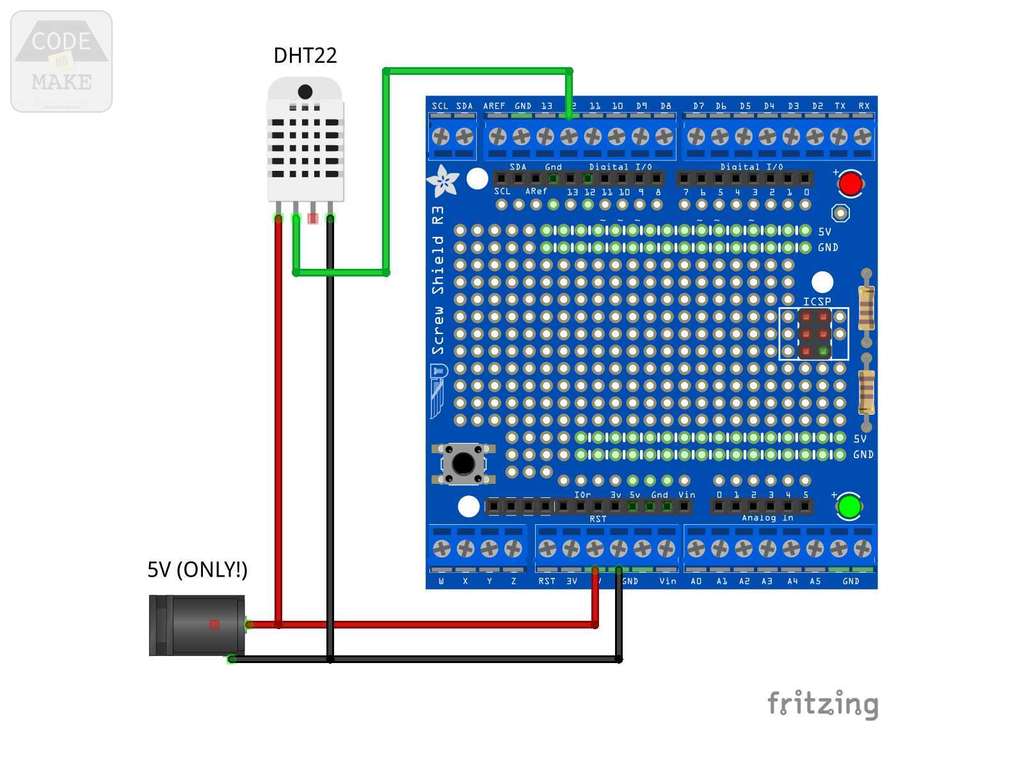 1) If you haven't already, upload the code to the Arduino...
prusaprinters
For the wiring please refer to the attached wiring diagram. The wires of the LED's are guided inside of the T-slot of the vertical aluminium profile and conducted through the designated opening inside of the electronics case. </p><p>A reflective...
myminifactory
Please use the wiring diagram as a reference. If you haven't already, upload the code to the Arduino (detailed in the 'Code' section above). Insert the Adafruit Proto-Screwshield (Wingshield) into the Arduino Uno. Remove the female pin header...
prusaprinters
Place the corner, screw, put the arms, screw, … · There is a hole for each screw, you can’t get it wrong. · For the wiring, please refer to the diagram. Firmware At this point all you need to complete the hardware part is to upload the firmware to...
thingiverse
Additional diagrams and photos --------------------- #### Charge amplifier for piezo-electric force transducer #### Power source --------------------- #### Full setup References ==================== * Herrel, A., Spithoven, L., van...