square hole pegboard hooks 3d models
446557 3d models found related to square hole pegboard hooks.
thingiverse
y-belt-guide-10mm-upgrade-rework-to-prusa-mk2.stl Mounting though hole size was enlarged to 11mm to fit M10 threaded rod, with part shrinkage in mind. Originally 9mm to fit 5/16th or M8mm all-thread/threaded rod. Not mandatory to replace from Rework...
prusaprinters
Within this, two holes are introduced through the entire valve block to allow overflow to drain into the channel.(Ventilation) The fit of the plastic tube has been optimized to 8x1.5mm, as from Toom. The connection's wall thickness has been reduced...
thingiverse
- 4x perimeters, 100% infill with **monotonic** infill - 0.2mm layer to have exactly 3 layers - Increase the overlap to avoid holes between the perimeter and the infill. My setting : 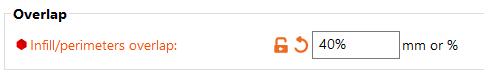 ##...
prusaprinters
So take it only as a fun. You will need printer with printing space of 240x190x190mm (Prusa MK2/3) is fine.Print SettingsPrinter Brand:PrusaPrinter: Mk2.5sRafts:NoSupports: YesResolution:0.2mmInfill: 5%Filament:Prusament PLA Galaxy Black Notes: I...
thingiverse
Standard bare bones, just a hole for the filament 2. Press fit for a bowden tube that bottoms out, that can be used as a filament guide. 3. Pass through for a press fit bowden tube, such that the tube can be cut to mate with the idler and hobb as...
prusaprinters
Using arms inspired by that project, and a Pi case taken from another project (http://www.thingiverse.com/thing:922740), I merged the two into a solid, effective mount for the Pi. Additionally, holes in the mounting arms can be used for mounting...
prusaprinters
It goes through the stick flexure.Snap the button-pushing arm into the holes under each face button. Add a bit of glue if they don't stay in well.</li><li>Stretch the face buttons piece and insert the tabs into the pockets in the lid piece. (The...
thingiverse
The answer was to recess the screw holes. I did that, printed it again, and added a small place on the top of the 25 mm mounting surface to store a full-sized SD card or microSD card adapter. Finally got it printed (see the pictures) and there is...
prusaprinters
Mount the bottom bracket (either side) to the side extrusion using one screw and T nut (the hole farthest away from the gantry is not use). Do not tighten it down yet (you want to wait until fully assembled to tighten everything in place). Then add...
thingiverse
Hopefully, there will be enough tests to start seeing artifacts from over-retraction, which will look like missing bits of layer, holes, or pits in the wall surface. Then you can find the midpoint between problems.** **Once you have a range (for...
prusaprinters
It might also need some sanding, as it is important that this part can move relatively freely through the (2) Base. (2) Base (3) Backplate (4) Frontplate (for Pi Shield) (5) Object Holder in different sizes you might need to use a 5mm drill bit to...
thingiverse
At the bottom of the bottom frame corner pieces are holes to accommodate 1/4" nuts and bolts. These are so you can add some sort of TPU feet to the print for vibration dampening. I intend to design these feet at a later date. The pieces for the...
cults3d
Instructions Y Axis (see picture below) - at exactly the center of 2060x454mm cut away an 25x20mm (HxV) portion of material - at exactly the center of 2060x437mm drill an 10mm hole Feet Glue circular shape 10mm thick rubber pads into feet bottom. I...
thingiverse
Go in to the original 3D files, remove the joyport wells, add the blanking pieces, and then use the joyport cut-out to cut out holes where you would like them to be - by default the cut-outs are located to the left side of the case. Of course...
thingiverse
###Filament change layer for colours on "PreludeBoxBack": 1) Start (Colour of the background, mine is in white) 2) Layer 14 (All logos outline colour, mine is in black) 3) Layer 19 ("Classic" lettering, Honda logo, "Honda" lettering and Honda...
thingiverse
The pencil area just seems like a platform with holes in it so I would add more design and make it more appealing and better. I believe some aspects, or the entire model might be too small so I would change the size and dimensions so it would 3D...
prusaprinters
You can also use DIN 933 / ISO 4014 or DIN 912 / ISO 4762 or something similar - OBI: around 0.5€[8x] M4 nuts - DIN 933 / ISO 4032 (B3a) or nyloc variant DIN 985 / ISO 10511 (B3b), any material however if you have a M4 tap then you don't need nuts -...
prusaprinters
Insert the blower motor into the fan holder body, taking care to route the fan wires through the smaller hole. Secure the fan cover to the fan body with 4* M3X10mm machine screws. 9/16" OD vinyl tubing serves as an air duct between the blower and...
thingiverse
If you are an expirienced artist you should be able to pull some 5rl type of lines at this speed.I recommend buying an rca connector and screwing it into the hole under the motor and wiring it up properly. You can then buy a cheap power supply and...
myminifactory
Start by inserting one of the inner wheels through one of the holes of the Body. Check to see if can rotate without too much resistance, but also doesn't wobble around. Put a dab of glue on the outer dial and press it into position against the teeth...
thingiverse
The hole bolt piece was another part for my personal choice, so I can add a threaded rod through a majority of the body to add both weight, and some rigidity strength to the model. If this is going to be something that hangs on a wall, I would not...
thingiverse
I have flown all three a lot, and lighter is always better to me, but the drill out holes near the motor mounts on the Lite are a little sketchy. Never broke mine, but I'm on the standard edition now, and am very pleased. I'll try to edit some video...
grabcad
The bracket itself is mounted via a single bolt hole at the top the bracket. There are two brackets, one on each end of the light. Once the brackets are mounted to a surface (ceiling, floor or wall), the light fixture can be removed from the brackets...
cults3d
(keep in mind that you will need to drill 3 3mm holes into it) 3 springs for print-bed (found those in CD-Rom drives) lots of 3mm screws or various lengths and nuts some cables for the stepper motors of the CD-Rom drives (i used old IDE cables, but i...
grabcad
The bracket itself is mounted via a single bolt hole at the top the bracket. There are two brackets, one on each end of the light. Once the brackets are mounted to a surface (ceiling, floor or wall), the light fixture can be removed from the brackets...
prusaprinters
Push it in until you see the bowden tube through one of the inspection holes. Then slide the screw cap along the bowdentube towards middle piece an thighten it by hand until they wont come apart. If you are used to it, you can leave the...
prusaprinters
Not offering this particular kit any more. 2016-06-23: Added missing tendon.dxf 2016-12-14: updated with new link to assembly and programming instructions. Support me through Patreon: https://www.patreon.com/imakerobots Or make a one time donation:...
thingiverse
This means that the screw holes for the mount are now part of the cable channel, but I added enough material to the channel to allow the screw heads to be fully counter-sunk. Dec 13, 2016: Well, the testing of the electronics box went faster than...
grabcad
The bracket itself is mounted via a single bolt hole at the top the bracket. There are two brackets, one on each end of the light. Once the brackets are mounted to a surface (ceiling, floor or wall), the light fixture can be removed from the brackets...
myminifactory
Only in one place you need to drill holes to a diameter of 3.1 mm. At this point, after this change, you will be able to use a screw and a nut instead of the screws from the original set. The biggest problem during design was finding the base points...